Icom don’t seem to like N-Type connectors. I have an X-50N Co-linear, with about 5 metres of Westflex 103 of which both ends are terminated with an N-Type plug. I used to have the Yaesu FT-897D, which is why I have the N-Type attached for VHF and UHF. Yaesu (at least in Europe) use N-Type chassis sockets for their UHF transceivers, but Icom use the SO-239, unless you buy something like the IC-9100. Since buying the IC-7100, I have been using an adapter.
Today, I decided to change the chassis socket on the Icom to an N-Type. Conveniently, there is no soldering involved. They have used a sprung clip to connect to the socket pin. Perhaps this helps prevent connection problems due to thermal expansion and contraction between the chassis and PCB or any movement in the connector pin itself. You could probably change it without opening the case, but its nice to see what you are doing and to know you are not bending the clip! Below shows the internal socket connections.
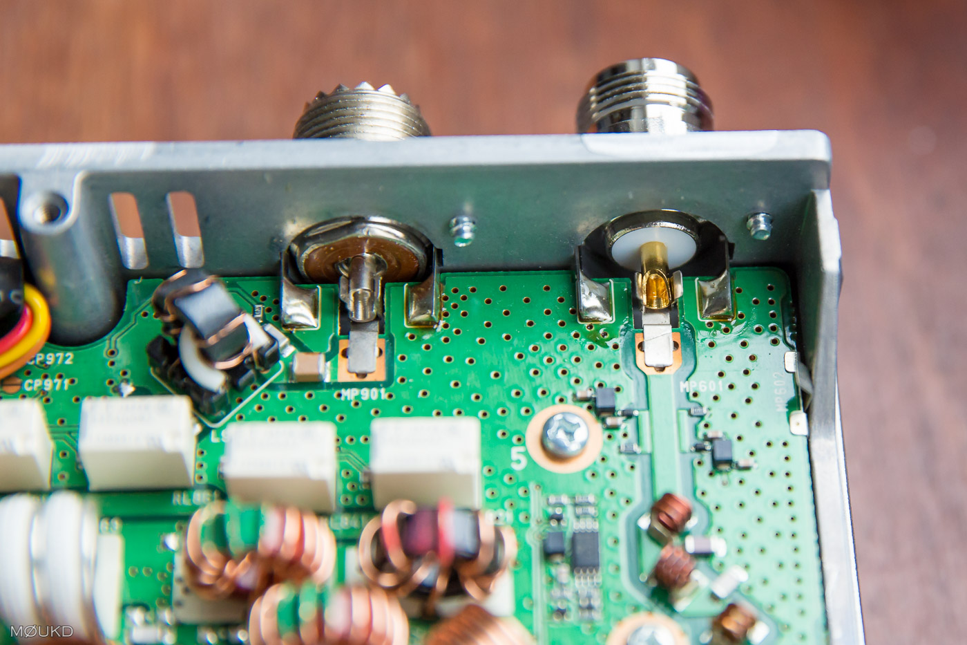
Icom IC-7100 RF Connectors
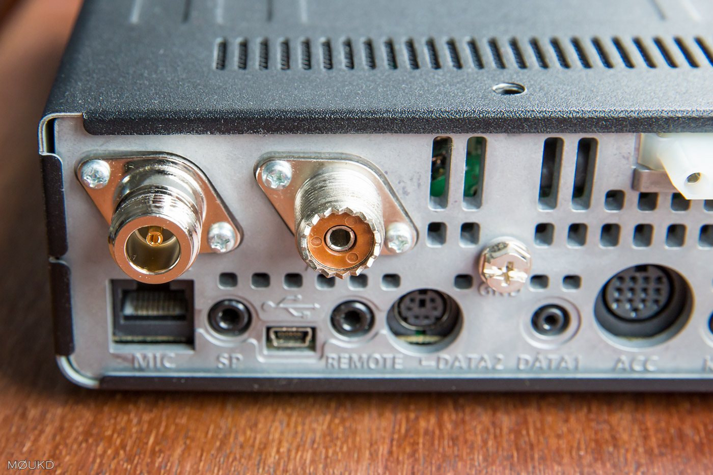
Icom IC-7100 N-Type fitted for VHF / UHF
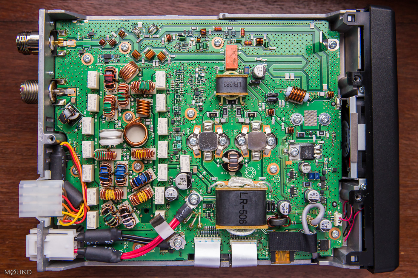
Before changing the socket, SWR was around 1.5:1 at 433MHz with the original SO-239 and PL-259 to N-Type adapter. After changing the socket to a plain N-Type and removing the adapter, SWR is 1.1:1 or better from 430-440MHz (Shown by the transceiver). It shows how critical things like connectors and adapters get at UHF, although most of the miss-match was probably the adapter. It also makes it easy to remember which port is HF and which is VHF/UHF. A mod well done. If only Icom built them with N-Type sockets in the first place! Oh, and whilst I had the lid off, here is a photo of the inside of the IC-7100 🙂
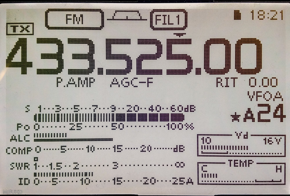
1:1 SWR after changing the chassis SO-239 to an N-Type socket
