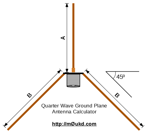
Ahh, the good old quarter wave ground plane! This calculator can be used to design a Quarter Wave Ground Plane antenna, with radials. The radiating element is a quarter wave (λ/4) and the radials are 12% longer. There are usually four radials, three being a minimum, but you could use up to six. This is a true unbalanced antenna, with a feed impedance of around 50Ω and therefore a great match to 50Ω unbalanced feedline. The velocity factor is set to 95% which should be fine for most people. You could cut a little on the large side and trim the antenna for best match at your desired frequency if you have the equipment.
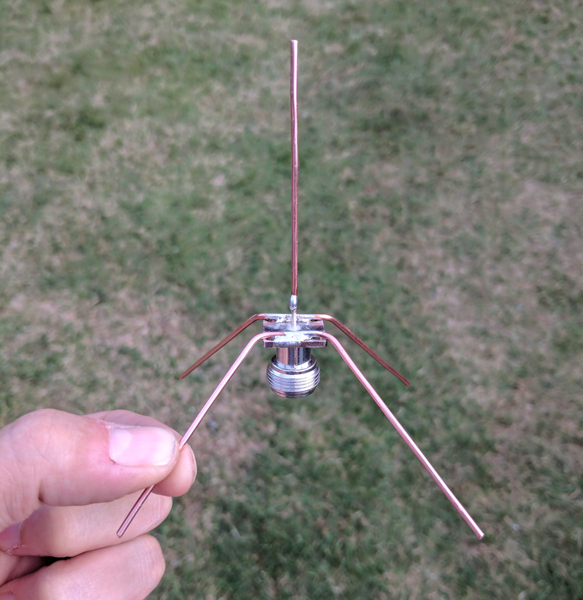
These antennas can easily be built for UHF or above by using a chassis mount N-Type (or SO-239) connector, some solid wire and solder. For VHF and below, as the elements get bigger, some more structured design is needed.
A quarter wave monopole mounted against a perfect ground will have an impedance of around 36Ω but by bending the radials down at an angle of 45°, we increase this to around 50Ω whilst at the same time lowering the radiation angle more towards the horizon.
Below is a quarter wave I made for receiving ADS-B signals on 1090MHz. I have made quite a few of these over the years and I will add more photos of quarter wave antennas that I have built soon.