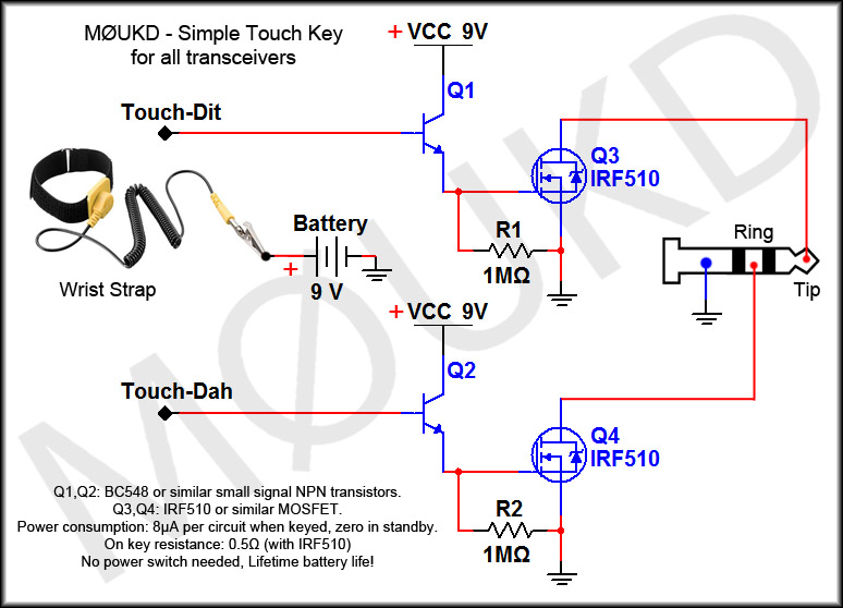
Following on from the simple CW touch keys in the previous page, this page shows a capacitive touch project which is the ideal touch sensitive key solution. The project described here is a iambic capacitive touch key which uses 2 AA size batteries for 3v power, draws <1mA current and has an ‘on’ switching resistance of <0.1Ω with a 3v supply.
The circuit diagram schematic is shown below.

Figure 1: Capacitive touch key circuit. Data sheets: AT42QT1011 | IRFML8244TRPbF
The circuit in figure 1 uses all surface mount (SMD) components. One reason for this is that the IC is only available in surface mount, but the reason for the use of SMD for the whole circuit follows:
|
When designing this circuit, I was going to power it with a 9v PP3 battery, through a 7805 5v regulator. This would have allowed the use of many logic level MOSFET’s, of which I was going to use the 2N7000 which has a TO-92 case. The problem with 5v supply to the AT42QT1011 is that at 5v, they draw around 1mA each. Add on the losses involved because of the 7805 regulator and overall, its just not ideal for power consumption. A transistor could have been used, but I prefer the use of a MOSFET to keep the circuit power consumption to a minimum and it saves adding a base resistor into the design. Also, there’s just something about MOSFET’s, isn’t there? Oh, maybe that’s just me!I did some tests at varying voltages for the current draw of both devices together plus the on resistance of the MOSFET at the corresponding supply voltages and the results can be seen in the table on the left. I decided that 3v would be a good supply voltage, which is easily obtained by two AA or AAA batteries, and the circuit would draw just under 1mA. The regulator would then not be needed and the battery capacity with AA’s would be much more than the 9v PP3. This means that the battery life using alkaline AA’s in this circuit is well over 3000 hours. Of course, you could use a 7805 5v regulator and power this from your 13.8v supply instead of using batteries if you didn’t plan on moving it around too much. |
The problem with using 3v is choosing a MOSFET with a low enough gate threshold voltage. Whilst searching for suitable MOSFET’s, it became clear there was no good candidate which was not SMD. Its a fact nowadays that SMD components offer much greater choice over their through-hole ancestors.
The MOSFET that I chose was the IRFML8244TRPbF which has a typical gate threshold voltage of 1.7v and a very low on resistance and comes in a SOT-23 SMD package. It was therefore decided to design the whole circuit around SMD parts. Many other logic MOSFET’s will work ok in this circuit, such as the IRL540, which comes in a TO-220 package and will switch up to 28A!
So, I had designed the circuit, tested the circuit, all that was left was to design the SMD circuit board, which I did with Eagle. The testing board I etched with photo resist PCB and developer. It worked fine and looked OK, but I decided as I had put the effort in to designing a board for this project, I would get some PCB’s professionally manufactured. The final design can be seen below. The PCB dimensions are 57mm x 37mm.
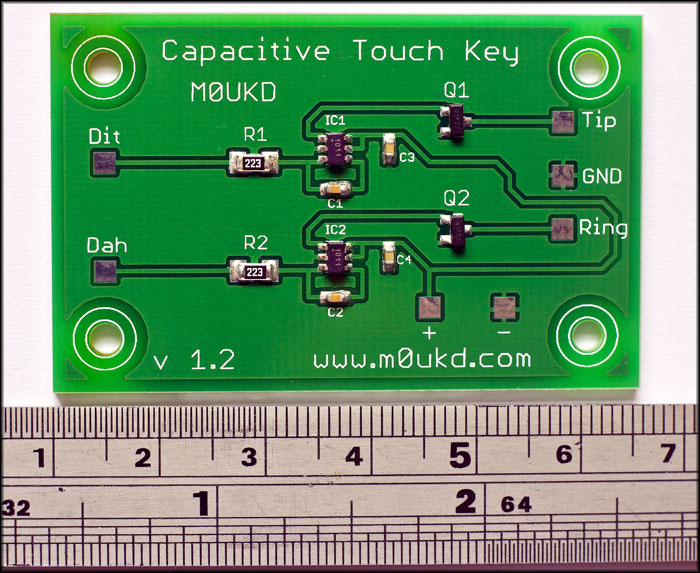
The completed board.
If you would like to photo etch a board yourself, a mirrored PDF file can be downloaded here. I have no boards left for sale at the moment.
Below is a video of how to solder the board using solder flux and hot air.
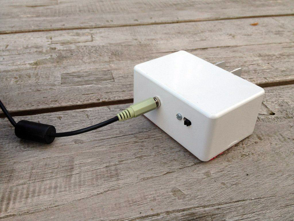
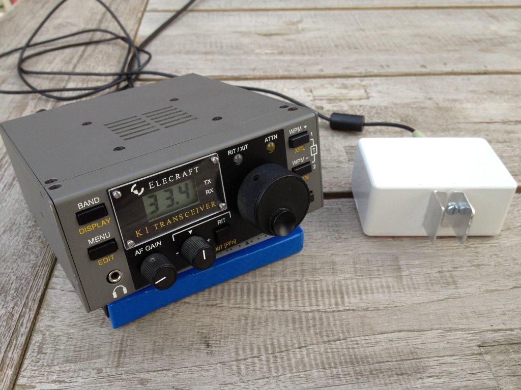
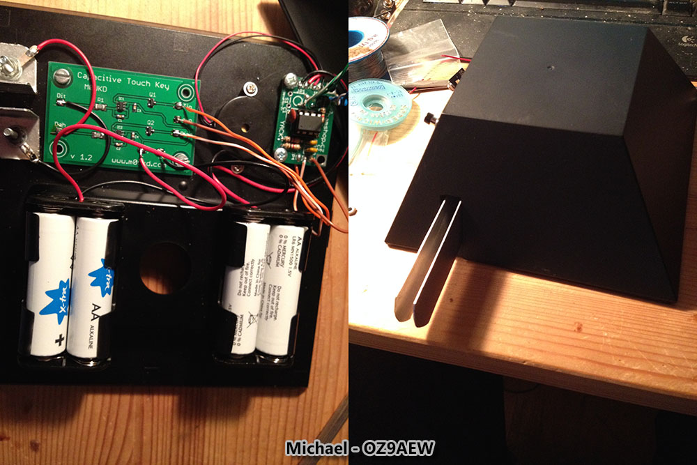
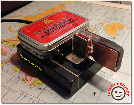
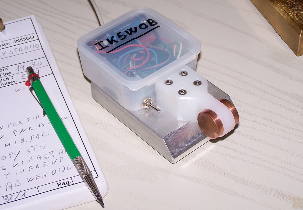
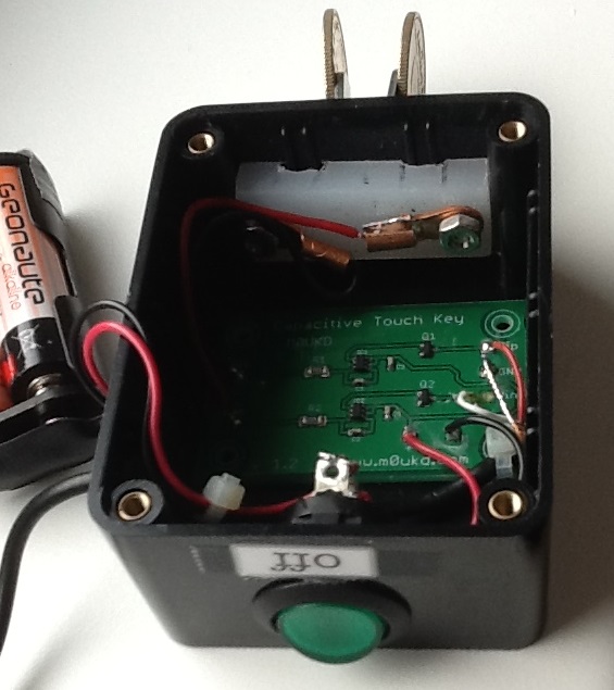
Below are some photos from people who have made keys with this board…
Below is a video from Stefano, IK5XCT who built the key. An interesting story is that as he says on the YouTube page, he had a contact using the key with DK7FH, who was also using one! Thanks Stefano!
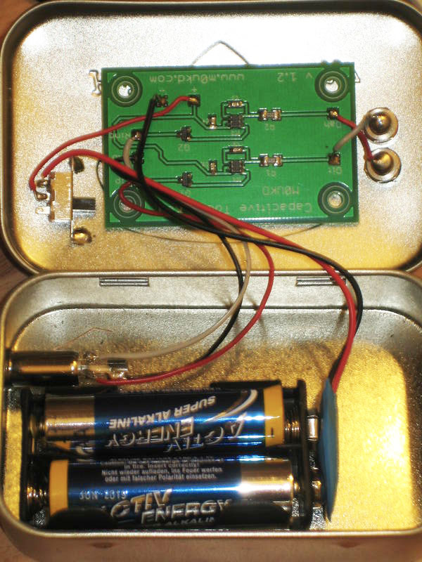
Frank DK7FH built it in a small steel container. He has some more QRP projects on his QRZ.com page.
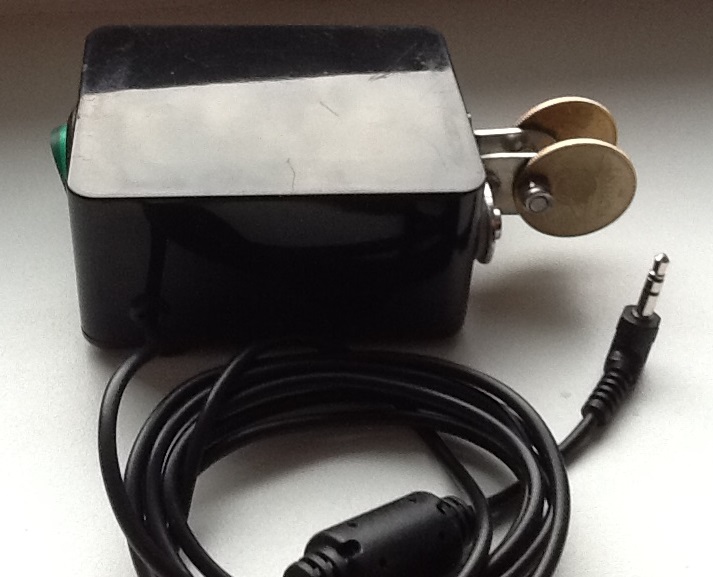
Istvan HA5CLF spent some money on his paddles! He used two coins for touch surface. They are 20 Ft each = 0.05 GBP!
If you decide to build any of the circuits listed on this page, I would be interested to know how you got on. Please drop me an email by going to the contact page. 73 de MØUKD.

