
Here is a low current charger I designed in an attempt to extend the life / recharge regular non rechargeable alkaline batteries. The trick to doing this is three things.
- Use a low current over a longer period
- Charge before they become too drained
- Charge to no more than 110% of the cells capacity (eg 1.5v charge to 1.65v and stop)
The nice thing about using alkaline batteries is that they have no internal discharge unlike Ni-Cd and Ni-Mh rechargeable’s, and are therefore suited to low current drain applications such as remote controls, clocks or things you don’t use often such as torches.In my tests I have found the lower charge rate, the better the charge and the less chance of a cell leaking electrolyte. Also, if a cell becomes too flat or completely flat, it will not take a good charge and will also probably leak electrolyte and possibly even pop open. The idea here is to keep them topped up. Lets say you have fresh batteries in a torch and you used it for a while. The cells have drained to around 1.3v for example. Put them on gentle charge with this circuit, monitor the voltage and stop when it reaches 110%. That would be 1.65v for one cell or 3.3v for two cells in series. Do not charge beyond 110% or there is a risk of cell leaking or even popping open / exploding. Its also advisable not to try to charge an alkaline battery that is completely flat. They don’t absorb a charge and just leak in my experience. Some of my tests I done outside in the winter (around 2°c) and I found the cells hit 1.65v quite fast but didn’t absorb much of it due to high internal resistance at cold temperatures. Charging should be carried out at room temperature, around 20°c.
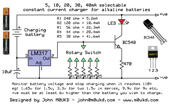
Here is a constant current supply circuit schematic diagram using the LM317 variable voltage regulator. It is a very simple circuit for charging alkaline batteries. It will provide a stable constant current which is adjustable by switching different values of resistors. The input voltage must be at least 6v higher than the battery(s) you wish to charge. The LED, BC548 and 470Ω resistor provide an indication of current flow to show that your battery connections are good. They can be omitted if you wish to make the circuit simpler. I used a 12 way rotary switch set to 5 way to select different resistors to give output currents of around 5, 10, 20, 30 and 40mA. The idea being for 9v PP3 types I would use 5mA. For AAA’s 10mA. AA’s 20mA, C’s 30mA and D’s 40mA. This is just my guideline, you can try what you like! Just remember more current is not good for charging alkaline non-rechargeable batteries.
You can use no switch and fix the current, or use a simple toggle switch to toggle between 2 or 3 different currents or whatever you prefer!
The constant current may be set by choosing the appropriate resistor. R = 1.25 ÷ I Where R is the resistor value in ohms, 1.25 the regulator’s reference drop voltage in Volts and I is the constant current in Amps. For example, if you want a 100mA constant current, the R value will be: 1.25 ÷ 0.1 = 12.5ohm. The dissipated power on the resistor R in this example is: P = V x I = 1.25 x 0.05 = 0.125W or 125mW. The dissipated power on the LM317 IC is:(Vin – Vout) x Charging Current. A heatsink is not required for the LM317 (TO220) in this low power circuit. If you design one with more than 40mA output current, you should heatsink it. Notice that the IC’s metal package or tab also carries the Vout, so it’s necessary to use isolating washers if you attach the heatsink to a metal case. High power resistors will be required over about 200mA but not needed here as we are using low currents to charge alkaline batteries! (200mA=1⁄4w @ 1.25v)
How this works: The LM317 keeps a constant 1.25v over the resistor regardless of input voltage or output load. This means when the load current increases or decreases, the regulator adjusts its output to keep a constant voltage over the resistor of 1.25V at all times and therefore a current of 1.25÷R.
One of the reasons this circuit is so simple is that most of the circuitry is inside the LM317 itself. It’s complicated circuit can be seen in its internal schematic diagram below:
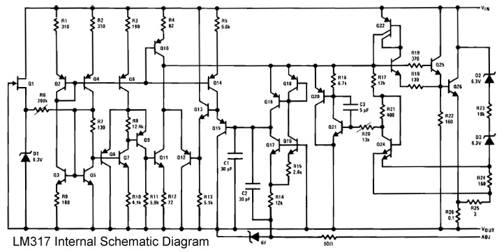
LM317 internal schematic
Yes that whole circuit is packaged inside the LM317. The three pins in, out & adjust can be seen on the left of the schematic. Inside are 26 transistors, 26 resistors, 3 capacitors and 4 zener diodes.
Disclaimer: Battery manufacturers clearly state that alkaline batteries should not be recharged. There is a possibility of leaking of chemicals / gasses and/or an explosion. Some alkaline batteries contain small amounts of mercury and/or cadmium. Always wear safety equipment such as gloves and goggles when experimenting with batteries, and clean up any spills of battery fluid immediately. Do not leave charging unattended indoors. Use this circuit at your own risk!
Works like a charm !!!
Thanks for sharing
exelente publicacion
You say monitor battery voltage and stop charging when it reaches 110%. Do you have to take the batteries out of the circuit to check the voltage?
Hi Jerry.
No, you can easily monitor the voltage whilst in circuit.
Good luck! John.
Assembled two chargers and it works great. Unlike NiMH/NiCd chargers, there is a minimal leakage risk due to small current. Although not shown in the schematic, you can create a DC source using a small step-down transformer (12 or 15V out, depending on your battery type) and a bridge rectifier. This creates pulsating DC current which is even better because alkalines experience less stress than with fully smoothed DC. I also recommend using 9-volt connectors for both the charger and battery holders because it will allow you to charge all types of batteries with no bare wires or alligators (which eliminates any chances of short circuit): you can easily and quickly swap your batteries.
Like before, a pulsed current charge circuit for alkaline batteries’
Thank you very much
Daniel Mansbach
like it Thanks for sharing