
Here is a formula and calculator for creating a loaded (shortened) quarter wave vertical or balanced dipole. The original javascript was created by Jack Ponton and can be seen here. As seen on his page, the original formula seems to come from an article by J. Hall, “Off-center loaded dipole antennas”, QST Sept 1974, 28-34. Please see the original javascript for additional references. The formula is below:
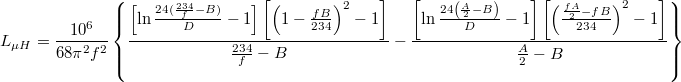
Original formula from QST Sept, 1974.
I used this formula and it seemed to work pretty accurately for centre loaded quarter wave antennas on the 160m band. The original formula was in inches and feet, so with Jack’s permission, I have modified the script to work with metric units, and this is presented below.
I need a cheap vertical for 10.1 mHz. I’m thinking a 102″ cb whip, base loaded. It will be based about 8′(~2.4m) on a wood gazebo frame, with radials snaking down from there. The gazebo is a Star Plate dome, from Stromberg Chickens.
You can try it, but 2.6m is quite short for 10MHz and base loading means there will be very little current in the actual whip. Still, it would be better than nothing! Good luck with your antenna building 😉
73, John.
Just do it
I run 10-40m mobile with what you are using or going to use..
If i can hear them i can work them, thats on 40m!!
Ie vk zs ja etc
HOWEVER try to keep all loses down and YOU WILL need to use matching at feed point
Also more ground the better 4 radials better than 1 etc
ALSO bigger dia the coil the better ( within reason) 2inch white pvc waste pipe seems to work well atleast up to 100w..mines filled with fibreglass..
If it is a quarter wave vertical, It needs counterpoise or a ground plane.
Please let me know what looks like your ground plane wire for this antenna..
Hi Yohanes.
Here, we are using a long wire mesh fence.
73, John.
Hi John, how are you?
Sorry for my ignorance, but the field “Wire diameter” is for the wire used for the loading coil? Or is for the diameter of the wire assuming your vertical (Or loaded dipole) would be done using wire?
(For example: If I’m going to build a loaded vertical with aluminium tube, should I put the diameter of the tube there?)
Thanks!
Hi Francisco. I’m good thank you!
The wire diameter here is the wire that you use as the antenna element, not the inductor. Yes, if you use tube, this will be the diameter of the tube. Just bear in mind, its a ballpark figure!
All the best, John.
“2.6m is quite short for 10MHz”? Isn’t actually 10cm too long?
I’m not sure what you mean by this. He was talking about 10MHz (30m band). I think you read it as 10m band.
Hi, John.
Thanks for the work.
Is very usefull, for who that like to try make his own antennas. Inductors are “mistic”…
In yours tests, how many the coil position affect the eficiency of the antenna?
Thanks,
Adriano,
PY3AK
Porto Alegre, Brasil
Hi Adriano.
I found coupling worked best when the primary was in the centre of the secondary, as pictured.
73, John.
Hi John,
I am very happy to find your web, since I want to build a short 80m antenna.
I would like ask you comment ;
1. If I use two different aluminium tube sizes (smaller size slides into the bigger one) for radiator, which diameter I should consider in above calculator?
2. I plan to build dipole antenna as the calculator described, which is better, vertical or horizontal polarization? The antenna intended for DX’ing. And I plan to raise it about 6-8 meter above ground.
3. Or, do you have other and simple design for 80m antenna for very limited space and capable for DX ing?
Thank you very much for your kind attention.
73′ YD1CZK, Soesanto
Hi Soesanto.
1. It would be difficult to calculate. You might have to experiment by adjusting the inductance.
2. I would go with vertical for DX. Not sure how you would do this though if its only 6-8 meter above ground. Elevation is key for DX work, to get the low angle of radiation.
3. Limited space and DX, it would have to be some kind of vertical. A loaded quarter wave made from wire on a fibre glass pole would be my choice for a portable setup. Maybe something more substantial for permanent outdoor use.
Good luck! John.
Jim, I stumbled upon your page here and it helped me build a nice 1/4 wave vertical for 6 meters.
I wanted an antenna on a top mount for my pickup, shorter than required for actual 6 meter 1/4 wave. I used your formula and wound the coil directly onto a cut-down Shakespeare VHF marine antenna cut to 30 inches and machined a stainless plug for the top with a hole and setscrew for a 1/8″ whip. It clears about everything. I finished the antenna after matching with a length of shrink tube to cover the lower section.
It matched up almost right out of the box. Thanks for the great info and easy to use formula.
Phil K2RRX
Hi Phil.
Glad you had success with a 6m 1/4 wave on your truck! Thanks for letting us know.
All the best, John.
John, I plugged in the values in your calculator
1.9 MHz
18 meter length of dipole
13.1 meter coil position from feed point
40 mm wire diameter
but got 95.5 uH, about half the 195 uH you got. Where did I go wrong?
Keith
Hi Keith.
I used very thin wire for the element, less than one millimetre. The 40mm element is the reason you are getting such a different result.
Cheers!
hi john,in the wire dia field,i thought it was the wire dia used for winding the coil,looks like its the dia of the actual wire that radiates ie the antenna element,what do we enter when the radiator is telescoping tube,ie tappered?,what do we enter then in the wire dia coil field? 73 Paul m3vuv
Hi Paul.
Yes, it’s the radiating element diameter. The top will be most critical so perhaps take an average of that and experiment.
Good luck, John.