
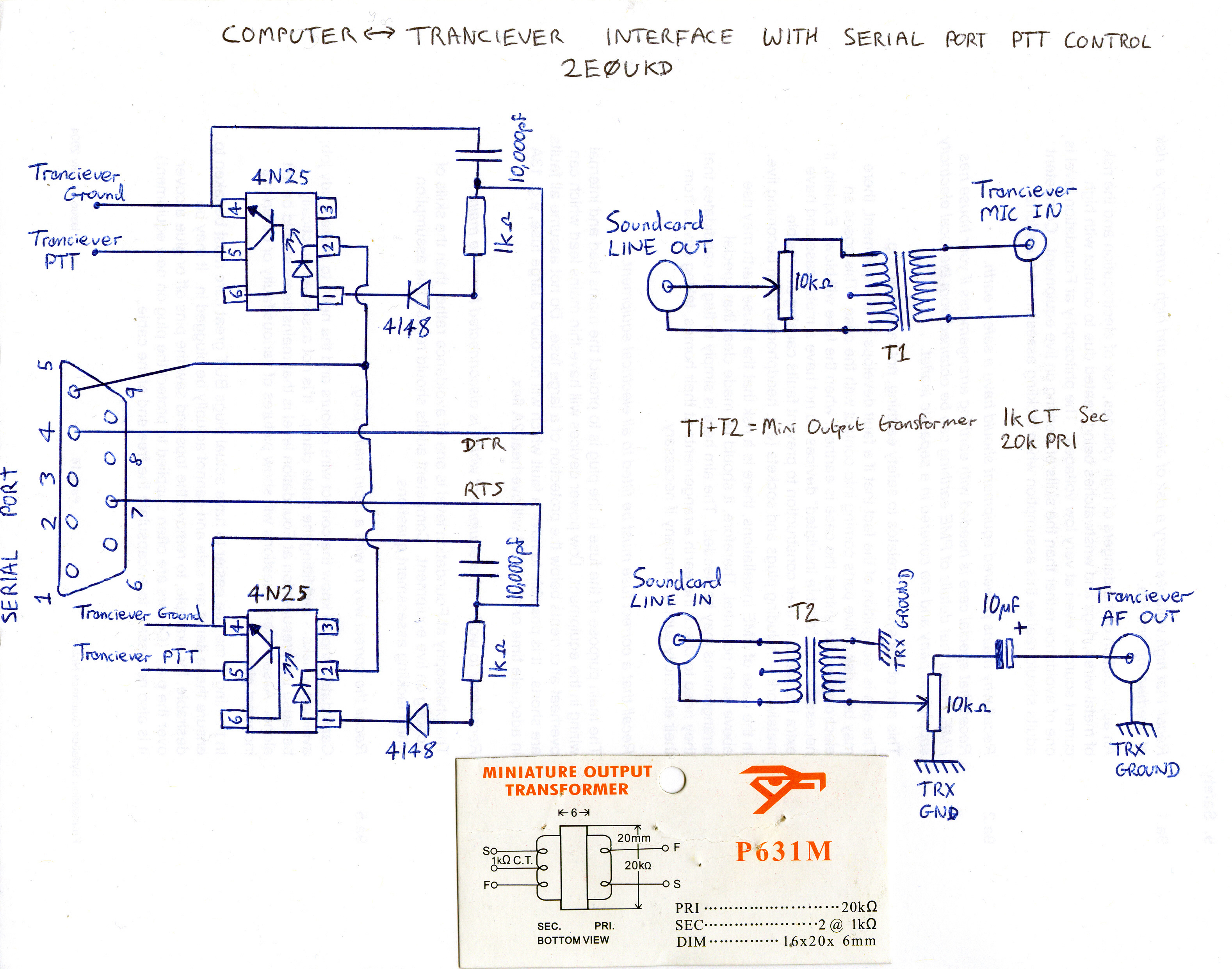
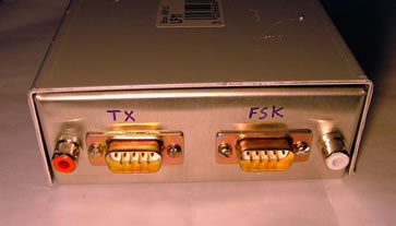
This was my practical project for the intermediate exam. It contains two isolation transformers, one for AF from the tranciever to the line in on a soundcard, and one from the audio out of the soundcard back to the mic / data input of the radio. Both of which are variable inside the interface via two preset resistors. It also contains two optocouplers, one to switch the radio to TX and one for RTTY FSK keying. The audio transformers I used are 20k primary, and a 2k centre tapped secondary. There is a few ways it can be used. It can be set so one serial port runs one optocoupler and another serial port can run the second, or, as its wired at the moment, one serial port can run both optocouplers. One RTS and one DTR. I previously used two for RTTY using the RTTY mode and FSK input on the IC-706MK2G, but now I just use the one with MixW and SSB. Works great with RTTY, PSK31, SSTV, Packet and I suppose any other data mode! Here is the original schematic, although it has changed a lot since then!
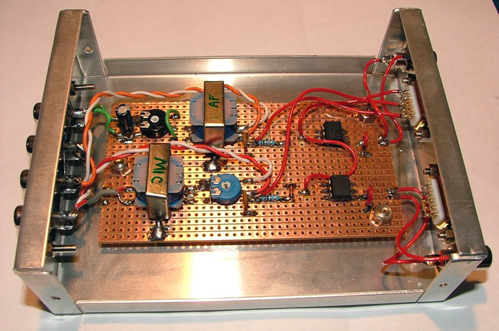
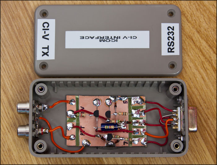
Inside the box
Update 2012!
This interface has gone through many revisions since I first built it in 2007. I had a MAX232 IC in it for a few years as a CAT (CI-V) link to the serial port. Pic of board below.
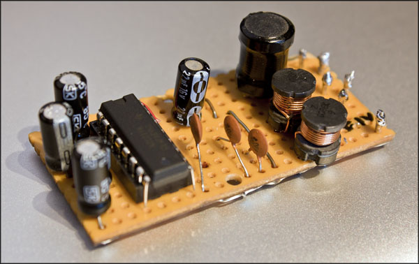
MAX232 CI-V Interface
The MAX232 was drawing 50mA and played up occasionally. I have now replaced this with a transistorised CI-V link, which can be seen in the photo below.
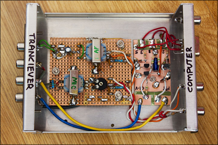
Updated 2012
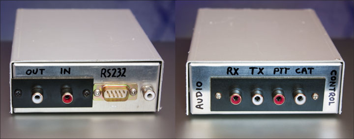
The original circuit board has been cut and the optocouplers are now gone, as I havent done FSK or used them for PTT for a long while. The new CI-V board on the right is powered from DTR (pin 4) and has an option for putting the radio into transmit through RTS (pin 7), although I almost always use CI-V for TX. The circuit used is shown below.
I was happy with this circuit, so I built another in its own box for portable use when logging with a laptop.
Hi John, Dave M0TAZ at Cray Valley last night suggested you might have experience of ptt switching an Icom 746. I’ve tried a similar cct off the web using a 4n35 but it doesn’t pull the PTT down enough to switch, but I will try your cct which is a little different. Seems my ptt has 8v and the opto can only pull this down to around 4v. Have you found this?
Hi Keith.
It’s been some time since I’ve used a 4N35 for PTT, but I don’t recall having any issues. I never measured the voltage on the PTT line, but I imagine it would need very little current to pull down to ground. Let me know how you get on. It would be easy enough to add a logic MOSFET in the circuit to make a low resistance switch, although I cant see why it would be necessary!
Good luck! John.