
I decided to experiment with Magnetic Loops. First, I tried something simple. A 145MHz 2m loop. Using the software at the bottom of this page, I worked out that a 36cm length of wire, will need a capacitance of around 3.6pf, and around a 50% efficiency. Making it any larger, and more efficient at 2m requires too small of a capacitor (eg 1pf and 70cm long wire loop, for an efficiency of 88%). Making efficient loops at HF is easier as the capacitance’s are larger and stray capacitance is therefore not such an issue.
So I tried some local contacts on the 2m loop, and was surprised at the results, even with it just poked out of the window. The trimmer is a 2-22pf. Its probably just OK for 5w or so. It will tune from 50MHz to about 200MHz, although tuning is fiddly because of stray capacitance of your hand, and also must be done with an insulated tool. An antenna analyzer is really needed for building this loop.
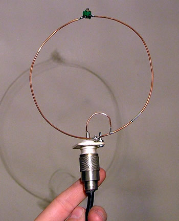
VHF Magnetic Loop (145MHz)
It is coupled by a small loop. It took some fiddling with different lengths to get it right. A Faraday loop this small was out of the question.This inspired me to build a bigger loop for HF!
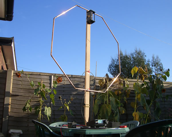
Here is what I came up with. Its made from eight pieces of 500mm long copper (4m in total). My air spaced capacitor is a dual gang 300pf, and im just using one gang here.
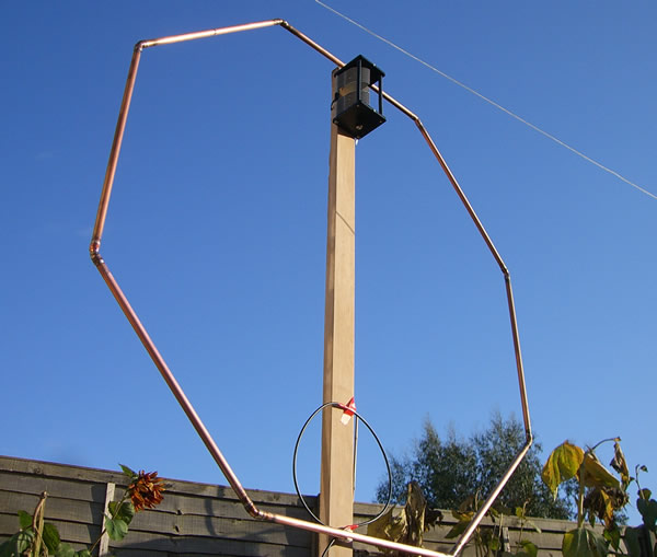
The Faraday loop must be one fifth the size of the main loop, and is not connected electrically. The main loop is 1.25 metres in diameter, so my Faraday loop is 25cm in diameter. It is made of RG58. I did try coupling by a ferrite ring first off, but it didn’t work correctly.
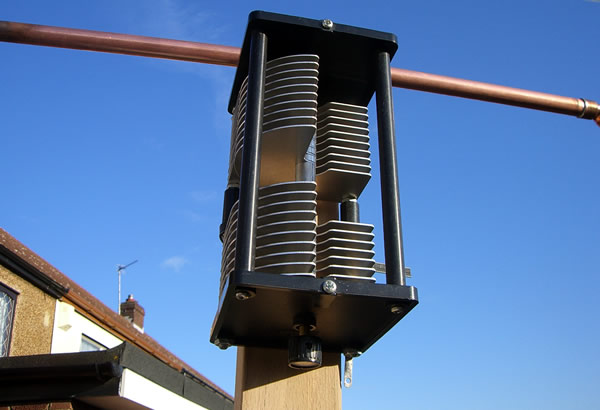
Here is my 300+300pf dual gang variable capacitor. It was ok to about 80w, it did flash over once at 100w.
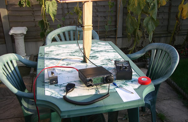
Here is my setup for testing on a nice sunny autumn afternoon! First contact was ON4MI, Michael in Belgium, on 7057KHz
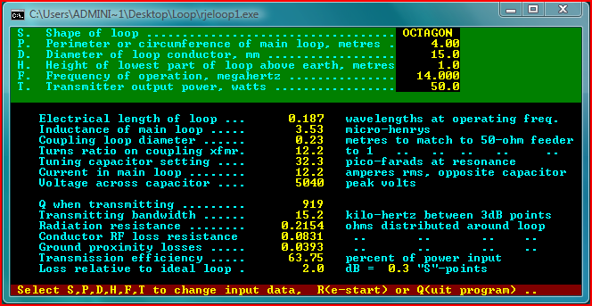
Magnetic loop design software
This is the handy tool that helped me decide what size loop to build in each case. The image below shows the information on my loop above, at 14MHz with 50w RF. You can download this handy tool from G4FGQ below.
| RJELOOP1.exe | Transceiving, single-turn, loop aerials of various regular shapes | by Reg, G4FGQ |
| RJELOOP2.exe | Transceiving, single-turn, loop aerials of rectangular shape | by Reg, G4FGQ |
Very nice project! – your design has inspired me, tnx es 73, de WR7R
Hi, was wondering if you have pictures or a diagram of how you connected the air spaced cap to the mag loop. Ive made my cap and have connected it how the designer has said but i cant get swr respone on my analyser….
Thanks in advance
Rich
Hi Rich.
It’s just connected at the gap at the top of the loop. As I used a dual gang, I had them both in series so the capacitor could handle more voltage. You need to get the loop resonant and have a suitable primary circuit. Might want to check those..
Good luck! John.
Hello from Tommy in Arkansas, just took at your design John. and it really impressive. I would like to build a loop antenna for 10 meter but i dont know how to calculate the measurements for it John, hope you could help me. and the size of variable capacitor that i would need to tune with. If you could help me with this would be greatly appreciated i have limited room where i live. My call sign is W5TGS. THANKU. Just email me the measurements and i would be forever grateful.
Hi Tommy.
Try using the program on the page, if you can get it to work. Good luck with your build!
73 John.
I cannot download the programme as I run a 64 bit System on My PC.
Where do I get a suitable Program????
Hi Derek.
As you say these are DOS programs and will not run on a 64bit system. Perhaps you can use an old machine (XP will do) or some kind of emulation or virtual computer.
Sorry I cant help, but good luck with your loop building! John.
I run the RJELOOP programs on a windows 7, 64 bit machine using DOSBOX which is a DOS Emulator. GOOGLE “Doxbox” to find a download source, it was free when I got it.
Bill W6SDI
Hi. Have you considered connecting only the fixed capacitor plates on your two gang capacitor and leaving the rotor ‘floating’? This has the effect of halving the capacitance while doubling the maximum working voltage. (capacitor sections in series). Even better, there is no lossy wiping contact. This is very useful, because any resistive losses in small loops have a big effect in performance. In the series configuration, all the RF flows through the capacitor spindle with none carried by the lossy wiper. 73 Al. GM1SXX
Hi Allan.
Yes I have done that as you say, but the photos are from when I was testing it and I wanted more capacitance for the lower bands.
Thanks for your comment & 73, John.