Here are some simple CW touch keyer circuits for making your own CW touch paddle key. The first circuit in Figure 1 is very simple, just consisting of two NPN transistors! It works by using the 50Hz mains voltage that is induced into your body by nearby mains wiring to provide a small base current which switches the transistor on just enough to key some transceivers in some situations. I say some, because you will likely need to be indoors and your transceiver probably needs to be connected to a mains power supply for this to work. It’s not ideal, but it is super simple and if it works with your setup, great! This is what I am using in the video below.
I have tested this indoors with three Icom transceivers, the IC-703, IC-706MKIIG and the IC-7400, all of which worked fine. The video above shows the super simple key being used with an IC-7400. The Icom transceivers will key with a very high resistance, which is why this circuit works with them. Try it if you use an Icom indoors or scroll further down for more options!
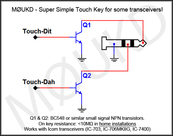
Figure 1: Super simple touch key circuit
OK, so what if you have a Yaesu or some other transceiver? Well, using the circuit in Figure 2 will allow a much lower resistance to key the transceiver than that in Figure 1. It is essentially the same circuit, but to increase base current, you connect yourself to the positive of the same power supply that is feeding the transceiver (note: positive 13.8v NOT mains power!) and use your body as a base resistor. This means you dont need the 50Hz mains induced onto the body, so it can be used whilst operating portable. The downside of course is you need a wrist strap (such as an antistatic strap) connected to positive. This gives a keying resistance of less than 1kΩ, which Yaesu transceivers seem to be happy with. I tested this with the FT-817 and it worked fine. The wrist strap can go on either wrist, ankle, or any part of the body really! Another option would be to make the key in a metal enclosure and hold it whilst keying. Neither option is ideal, obviously!
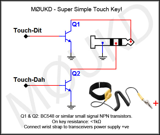
Figure 2: Super simple touch key circuit with wrist strap
So, what if 1kΩ is not low enough for your transceiver? If you are going to have a wrist strap, you may as well build something that switches on with a very low resistance, so lets throw in a MOSFET after the transistor and include a 9v PP3 battery to assist in base current. The circuit in Figure 3 will provide a key resistance of 0.5Ω which will be low enough to key any transceiver, or even switch it on and off! This may be preferred to the circuit in figure 2 anyway, as it means you can plug the wrist strap into the box that the key is built into, rather than running a cable to the power supply. A simple bannana jack could be used. No power switch is required, as the circuit draws zero current when unkeyed and an incredibly low 8µA per circuit when keyed (8µA is 0.008mA). The power consumption of 8µA is because of the 1MΩ gate discharge resistor. This means that a typical 550mAh alkaline PP3 should last almost 8 years of continuous keying!
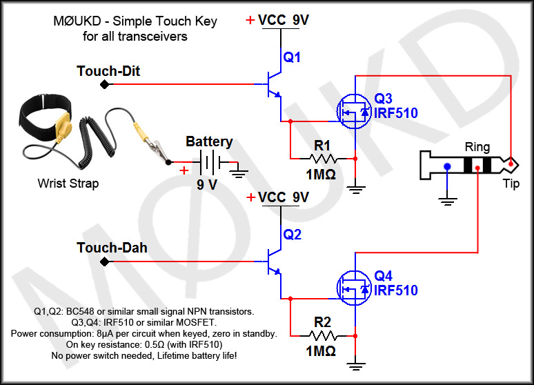
Figure 3: Simple touch key for all transceivers.
Components are not critical. Many different types of MOSFET can be used. The IRF510 is overkill for this requirement, but its cheap and has a very low on resistance of 0.5Ω. I also tried an IRF540 which has an extremely low 0.07Ω on resistance and can switch up to 28A at 100v!
Logic level MOSFET’s such as the IRL510 may also be used and these will happily switch on with only 3v gate voltage. If a logic MOSFET is used, you may if you wish, substitute the 9v PP3 for a 3v lithium cell such as the CR2032. Old motherboards provide a good source of logic level MOSFET’s, although SMD types. They can be easily removed with a small flame torch. Just google the part numbers!
A very cheap logic level MOSFET for this project is the 2N7000, which has an on resistance of 5.3Ω but you can buy 10 for around £1.
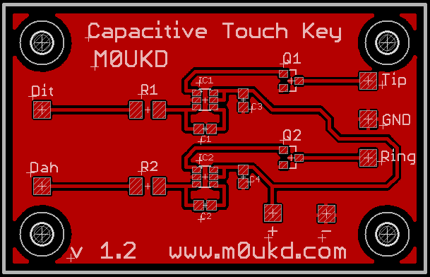
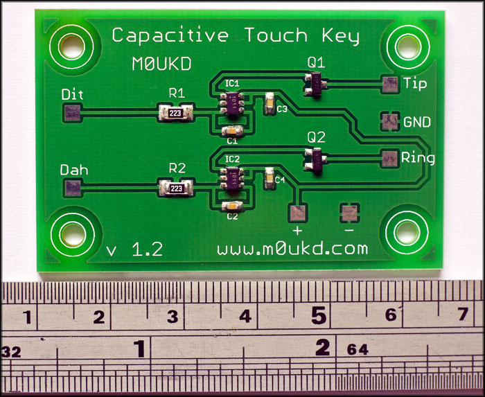
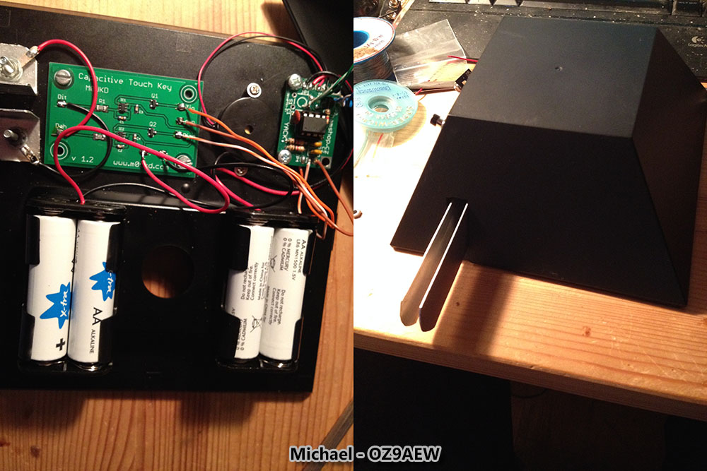
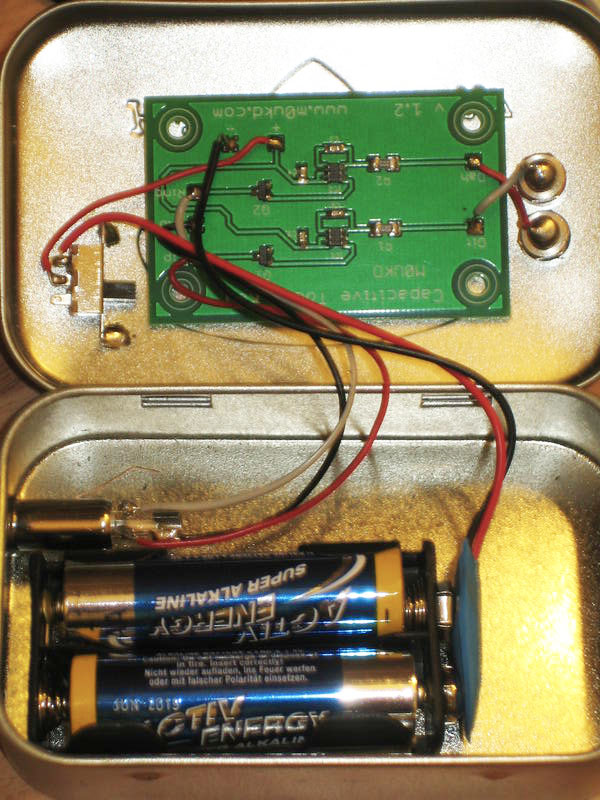
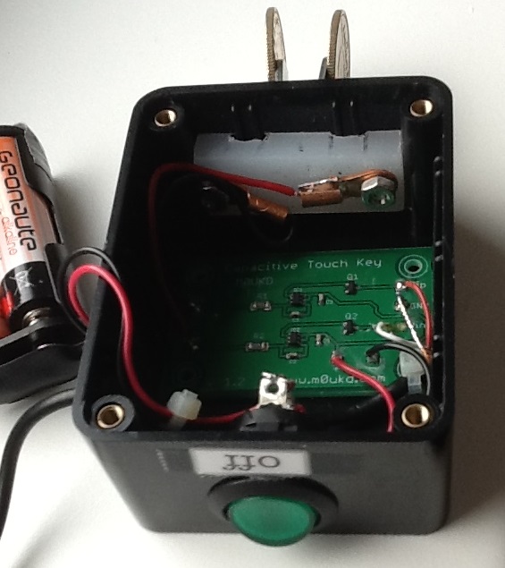
OK, so how do we make a CW touch keyer without an annoying wrist strap? Capacitive touch is the answer! The circuit below uses all surface mount parts, and this project has its own dedicated page!
Click the circuit below to view this complete project!
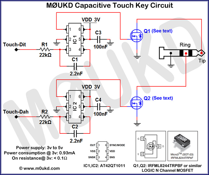
Capacitive Touch Key Schematic. Click to view project.