
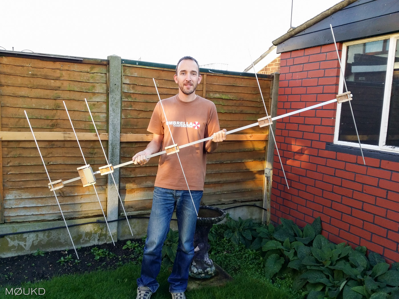
Version 4 of the portable beam, the ‘PegTenna’!
This page contains construction details on a 2 metre 144MHz VHF Yagi beam antenna, designed for portable use. Since an old 5 element version (v1) of my antenna was shown in the July 2011 edition of RadCom, a few people have contacted me asking for some information on how it was constructed. It has gone through a few revisions over the years (this is version 4) and is now a 6 element Yagi Uda (poor Uda never seems to get a mention), based on a DK7ZB design, with a little tweaking in EZNEC.
The challenge for this antenna was that it had to be compact enough to walk up a mountain and be very quick and easy to assemble and disassemble. 6 elements was chosen, as the boom length is 2m (6.5ft) which keeps it portable, whilst still having good gain. The next problem was how to build it so it can be put together quickly. After a lot of thinking, I decided to use wooden clothes pegs to mount the elements and driven element. Previous versions I have made used large screw terminal blocks, perspex, plastic booms, but this is certainly the best version so far!
Note: The version I built, as described on this page, is optimised for SSB at the low end of the 2m band (144.3MHz) and will not be suitable for using at or above 146MHz. Bill, VE7WNO built this Yagi and observed the SWR shot up above 146MHz (see SWR plot above 146MHz here), so I have designed a version of this antenna centered on 146MHz for more broadband coverage of the USA/Canadian allocation of 144-148MHz. The dimensions for the all band coverage version can be seen here and SWR plot is here. It also uses ¼” tubing (6.35mm) instead of 6mm. See Bills comments at the bottom of the page for more info. OK, on with the 144MHz build…
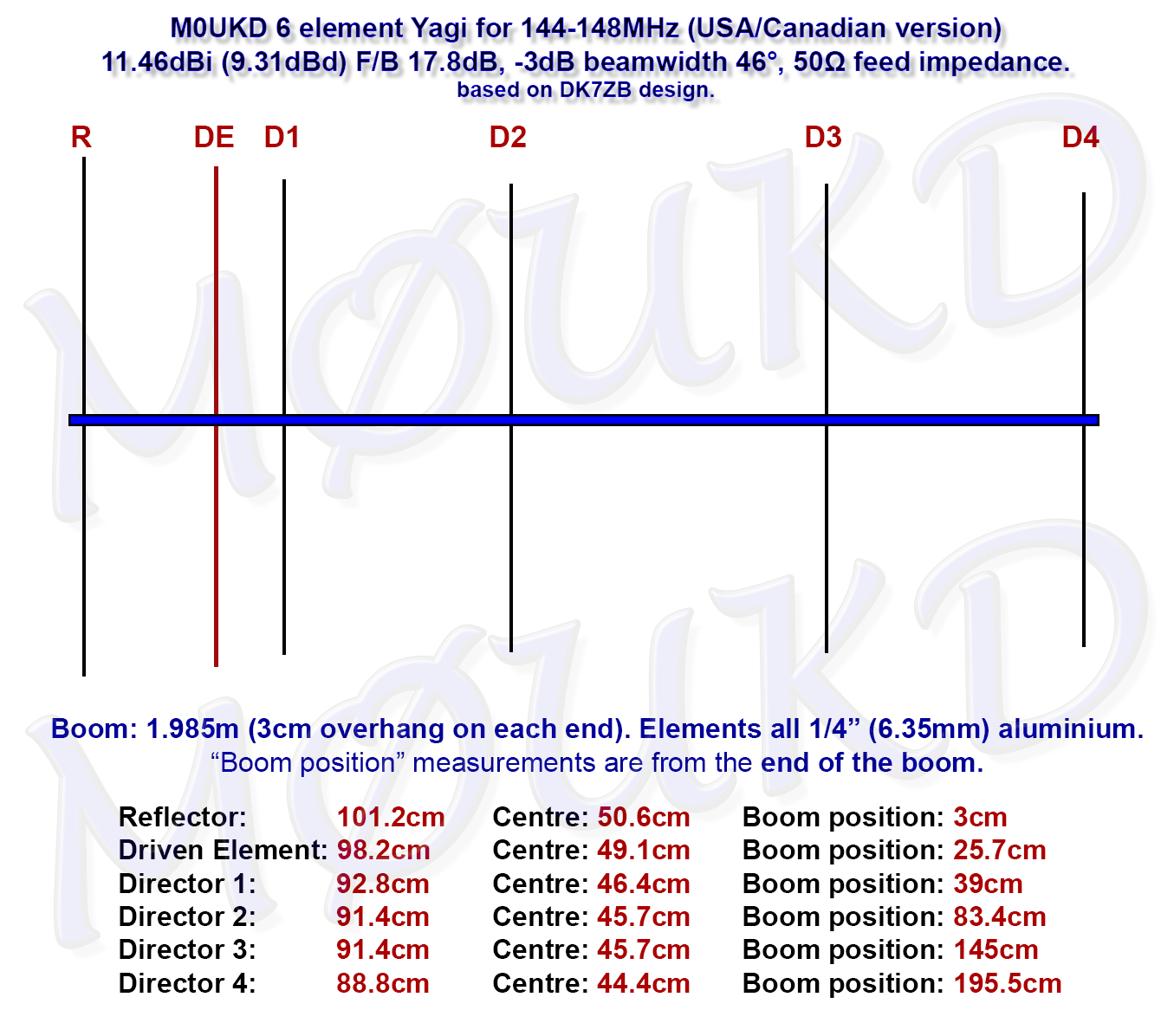
The dimensions are below:
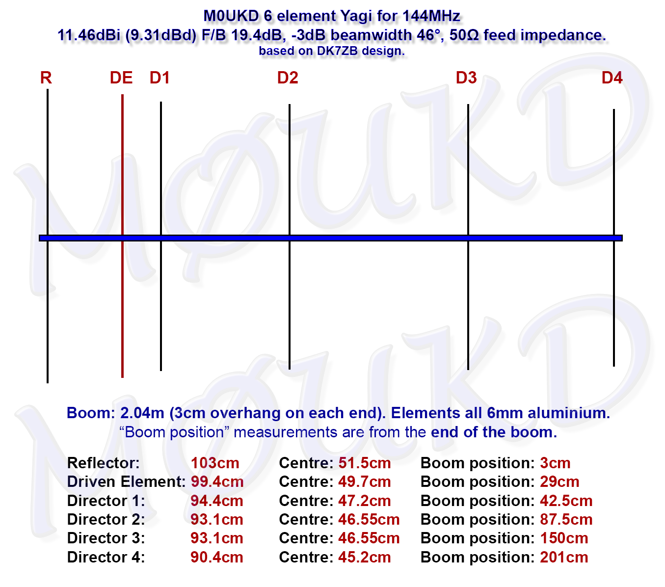
The dimensions of the 2m beam antenna, centered on 144.4MHz. Click for a larger image.
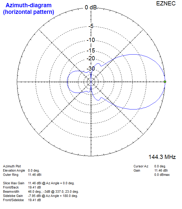
Horizontal radiation pattern
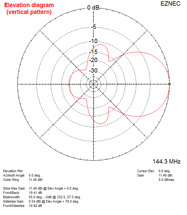
Vertical radiation pattern
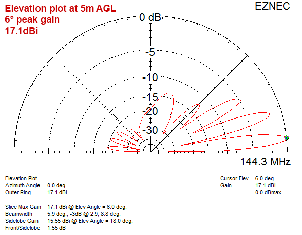
Elevation plot with the antenna at 5 metres above ground, for example in a portable set-up. Peak gain 17.1dBi at 6°
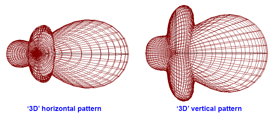
‘3D’ view of radiation pattern
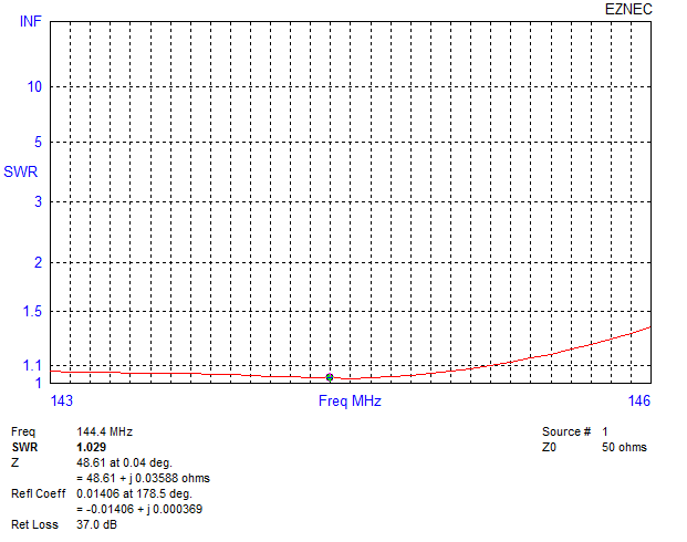
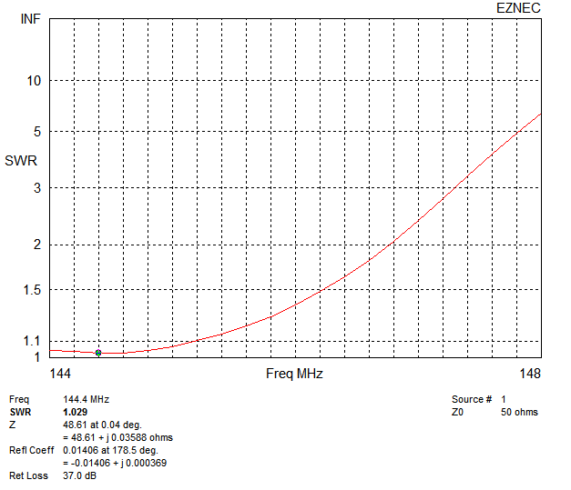
SWR plotted from 143MHz to 146MHz with cursor at 144.4MHz.
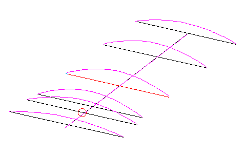
Antenna currents
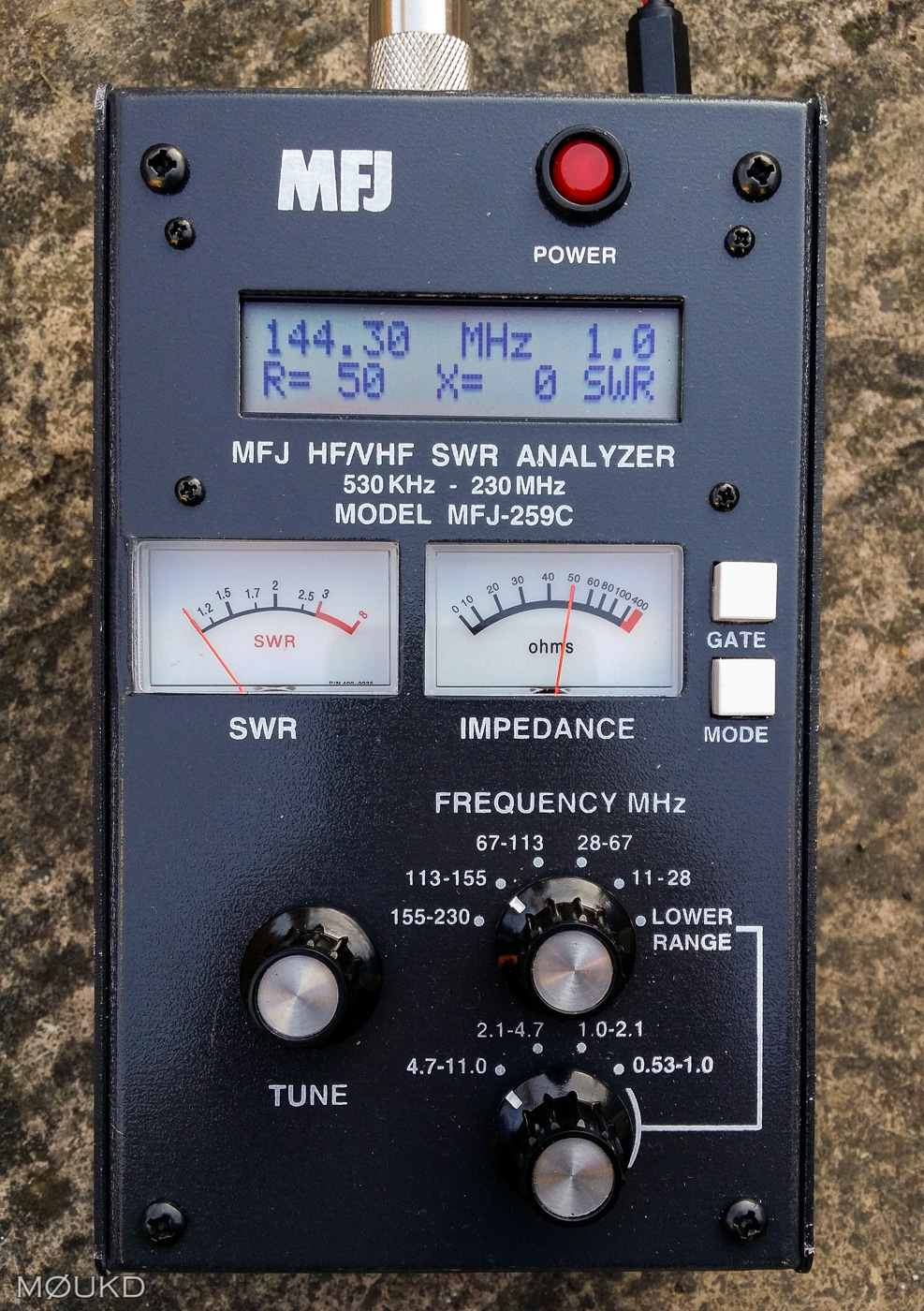
First test with antenna mounted 3m above ground. Very happy to see this on the analyser! Never seen it like this before on any other antenna.
Of course there are many ways to fabricate a Yagi antenna, but hopefully this page gives you some idea of some options. Below are some photos showing in detail how the antenna is put together.
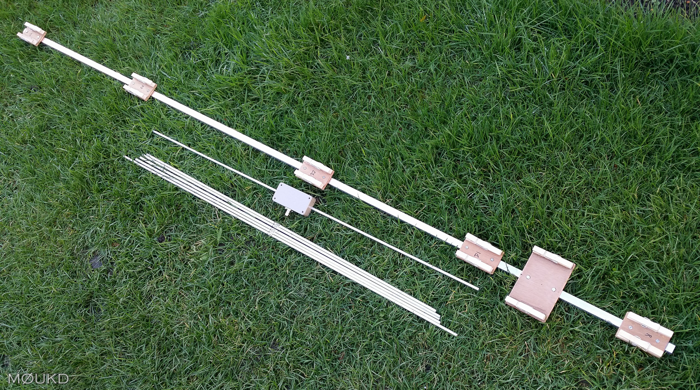
The antenna disassembled. It can be put together in 30 seconds!
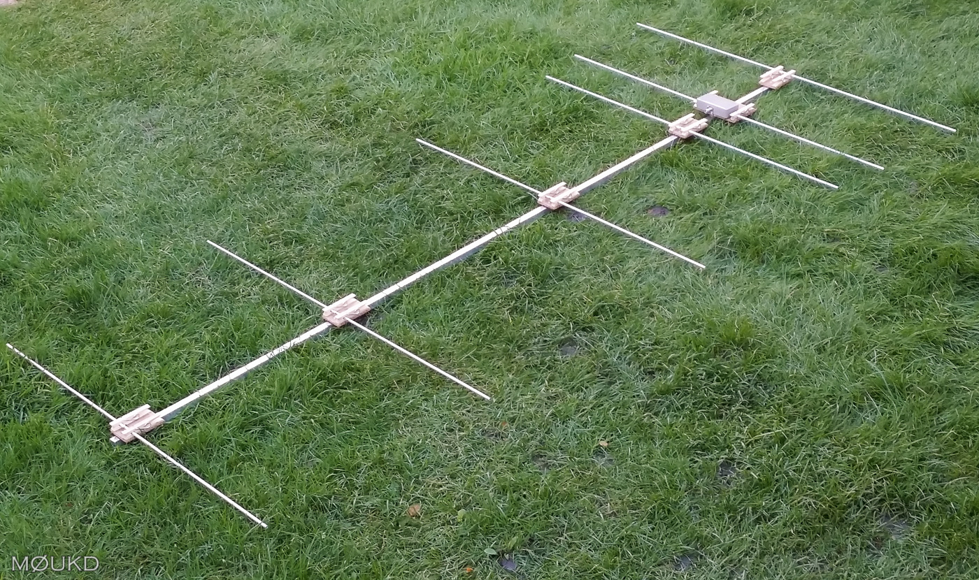
The assembled Yagi.
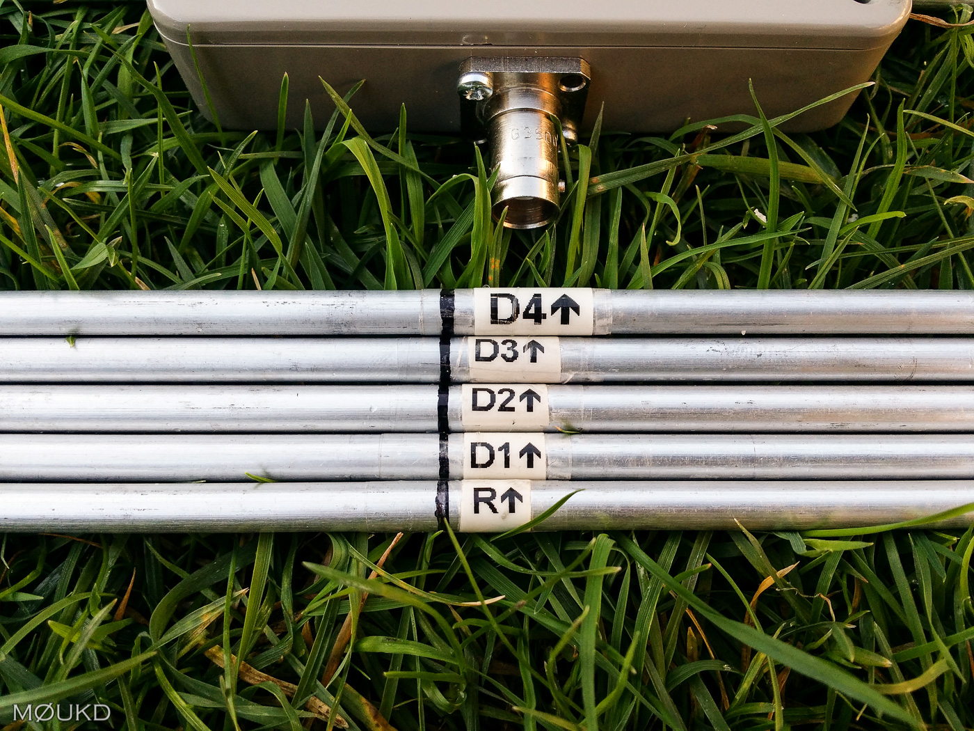
The elements are numbered and marked with a black centre line for ease of assembly.
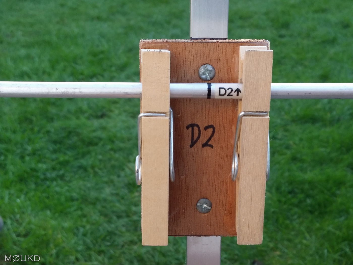
An element in place. The black line is centred to the screw, which is centred to the boom.
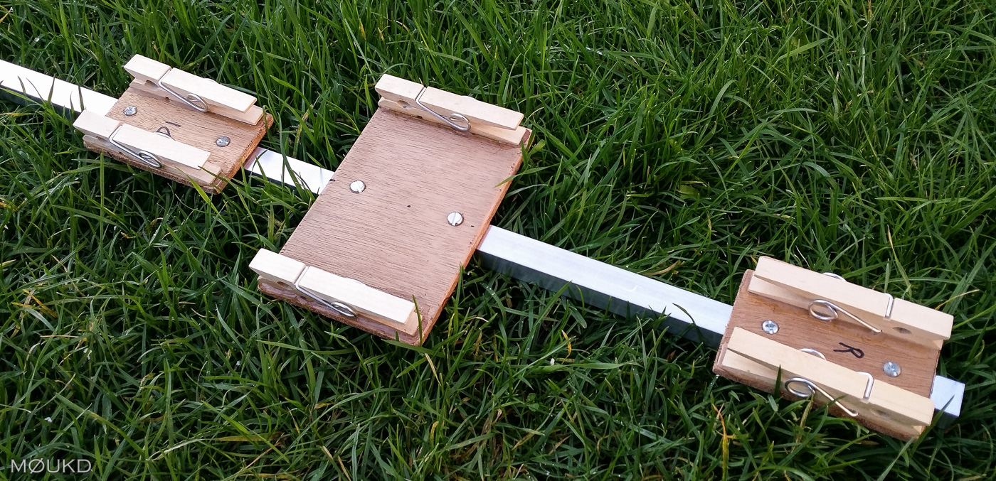
The driven element has a larger plate to accommodate the box which contains the choke and driver assembly.
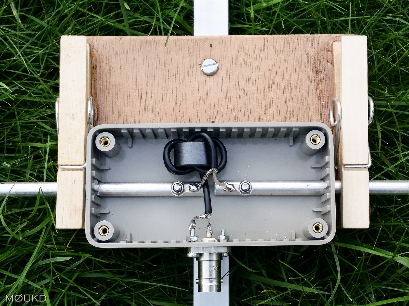
I have used an unknown ferrite with 4 turns of RG174 as a common mode choke. I first tried a small air wound choke, but it was not very effective. I have yet to test this method with 100w of RF power, but I think it will be OK.
Gil, F4WBY built this antenna to use with his new Icom IC-251E and made a video of his build, which you can see below. Cheers Gil!
Some photos of using my original homemade Yagi are below. I shall add some of the new one shortly!

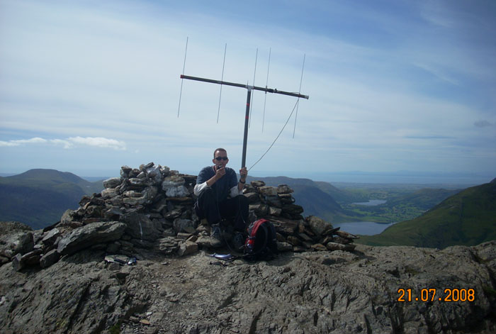
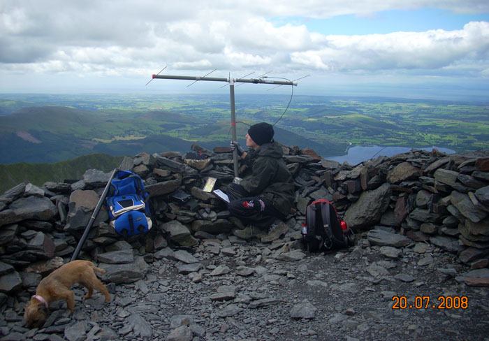
John, M0UKD on the highest point in England, Scafell Pike.
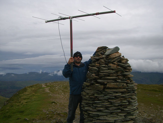
Dave, M0TAZ with version 1 of the beam on the summit of Dale Head.
John, M0UKD operating on FM with version 1 of the beam orientated vertically. Summit is Robinson.
John, M0UKD on Skiddaw with version 1 of the beam.
If you decide to build this antenna, I wish you good luck. I would love to hear your results if you do, please get in touch! John.
Hello John
I received my Amateur Radio license in November of 2013, and this will be my first antenna project. Most of it seems pretty straight forward, but I am having a little trouble with the driven element. Do you have dimensions for the Plexiglas, I believe it is 6mm thick maybe 30mm by 96mm? Does the center of the driven element rods need to be on the same plane as the reflector and directors, as it seems from the pictures to be slightly above them. One last question, where did you source the terminal blocks from? I am looking forward to using this antenna for SOTA events here on the west coast of Canada and this looks like the most reliable means of connecting the driven element I have seen on a portable antenna. As a new ham I appreciate the site, and look forward to more projects.
73
Bill Northcott VE7WNO
Hi Bill.
The plexiglass is about what you said, whatever you need to mount the elements on whatever boom you are using. Ideally, on the same plane, but at VHF, a few mm is not going to hurt. The terminal blocks are just regular terminal blocks, but with the brass part removed from the plastic. I’m not sure if the ones we have here in Europe are the same as the ones you use over there.
Good luck with your antennas. I will update this page as I’m now on the 3rd revision of this antenna. It now uses an aluminium boom and has 6 elements.
73 John M0UKD.
Hello John,
Great looking antenna! I am wondering how you attached the wooden clothes pins. The pics look like a hot glue gun was used but I’m wondering if a wood glue such as Liquid Nails would be better? Another advantage I see is if the outer part of any of the clothes pins break or get lost that it would be a piece of cake to slip another one into the spring so a couple extras could be carried in the kit. I’m currently waiting on a neighbor to take down his television aerial which he has graciously agreed to give to me when he has roofing work done this Spring. (He didn’t want to go thru the trouble of disassembly for proper disposal). Anyhow, Thanks for design and I’m looking forward to my first attempt. I’ll have to see if I can borrow and analyzer from a member of our radio club and once I do I’ll come back and let you know the results and have some pics for you.
73 Bill KM4AOF
Hi Bill.
I used two part epoxy resin to attach the pegs. It allows a minute to square things up. I attached the pegs to the element, mixed some epoxy, then glued the pegs down to the wood with the element clipped in them so I could square it up 90 degrees to the boom.
Good luck with your build, would like to see some photos of the finished antenna and hear how it performs!
73, John.
This may be a stupid question, but understand I never built an antenna. What is the boom diameter or does it not matter? You mention all elements are 6mm. Lastly, can I purchase a ferrite that would work?
Hi Mike.
Boom diameter is not too important at VHF, however a smaller diameter is always better. I used 15mm square aluminium box section as its small but very strong. The ferrite is from the junk box, so i’m not sure. I don’t think its too critical, i’m sure the antenna would still work well enough without it.
Good luck, John.
Hi John,
Just got a few stupid questions about your Portable Yagi antenna.
Noted the TOTAL LENGTH, of the DRIVEN ELEMENT is 99.4cm (994mm).
Also noted that there is a gap between the two element when they are mounted in the little connecting box…looks like about 6mm?…Is the TOTAL LENGTH still 994mm with the gap included?.
Then the coaxial cable lugs, are not on the edge of the element…how far are they from the edge?.
Does the two little mounting bolts, on the DRIVEN ELEMENT go through the box?
Wonder if you could clarify these few questions for me?
And congratulation on a winner-design!
Regards,
Andy Swanepoel,
East London, South Africa.
Hi Andy.
The gap is not included, so the 994mm is tip to tip. If you make a larger gap, the coax will become the element anyway.
I would keep the lugs as close to the edge of the element, without weakening the hole. It’s not too critical at VHF.
Yes, my bolts go through the box, but they only touch wood on the other side 🙂
I hope that helps, and I’d love to see some photos of your completed antenna if you decide to build it!
73, John.
Hi John
I finished my antenna Wednesday evening and started testing yesterday, although I wont have access to an SWR meter until tomorrow. I am curious as to what you are using for a mast, as my antenna has already been drop tested (long story). I keep spare clothespins on hand, I used Plexiglas in place of the plywood and fastened the clothespins with contact cement. After I put everything back in place after the drop test I made a contact through a repeater that is 85km away with the antenna on a 5 foot mast. I have taken some pictures, which I am not sure how to share with you on here. I am going to try and get the antenna onto a 10 foot(3 meter) mast of 19mm id PVC pipe and see what happens. I was trying to contact people on FM simplex on 146.520MHZ but had no answers last night. I will keep you posted, as the intent is to take this antenna on our next SOTA outing. 73
Best regards
Bill Northcott
Hello John
Got a chance to test the antenna this past Saturday, one contact that I made on FM Simplex was 160 kilometers away. The one thing we noticed in hooking the antenna to an SWR meter, at the lower part of the 2 meter band, from 144mhz to just under 146mhz the reading was quite good, about 1.2 to 1.3. However, once we got over 146, the reading went from 1.5 to 4 at about 147mhz. It was suggested that I try trimming about 4mm off each side of the driven element and retest to see how that effects the SWR. I would be very interested to hear your thoughts on this. 73
Best regards
Bill Northcott
Hi Bill.
Most of the time, I use the antenna with a short plastic pipe as a mast and hand hold/rotate it on small hills in contests. Nice to hear you got it working between 144-146MHz anyway! I have not looked above 146MHz with this Yagi, as we only have a 2MHz allocation here in the UK from 144-146MHz. It is designed more for gain than bandwidth, as everything is a compromise. It is centered on 144.3MHz also, as thats our SSB centre of activity.
I plotted the SWR in EZNEC, and as you observed, after 146MHz, it shoots up as below:
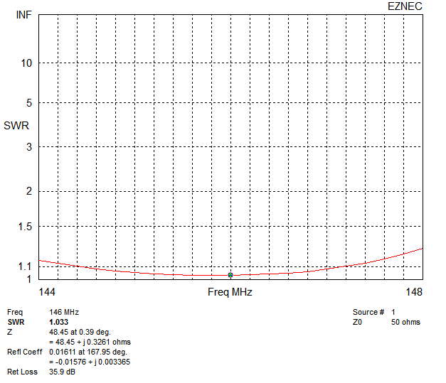
I have rescaled the antenna to centre on 146MHz so it is more suited for all across the 144-148MHz USA/Canadian band and this is the new SWR graph now:
It still shoots up before 148MHz but should be much better if you want to cover more of the USA/Canadian band. If you want to modify your antenna, all elements are slightly shorter and also slightly closer together. The dimensions for this new version are:
I’d love to hear how you get on if you decide to try the re-scaled version! Hope it works out for you and sorry for not thinking about your huge 2m allocation 🙂
73, John M0UKD.
Hi John
I will try trimming the elements first and see how that goes. I have had a hell of a lot of fun building this, and got compliments from some of the older members of our club. The clothes pins really make setup fast, and also make for easy repairs if needed. I will keep you posted on how things go. The antenna is quite directional, and even though centered on the lower end it really gives gain, considering I am using it with a Baofeng UV5R handheld putting out 4 watts. Thanks again for all your help, I see you have some other projects on your site, so back into the workshop I go. 73
Best regards
Bill Northcott
Hi Bill.
Trimming 4mm off each side will help, but it is not the best thing to do.
I would go with the rescaled version if it’s possible!
Good luck, John.
I’m curious – Would the diameter of the elements make a significant difference if I used 0.25 inch (6.35mm) aluminum instead of your 6mm? The 0.25 inch would be much easier to get here in the US. I really want to build this and use it for mobile operations, looks great!
Hi Brandon.
It would make a slight difference. To compensate for it, take 2mm off the length of all elements (1mm each end) as crazy as that sounds! You might want to build the 144-148MHz version, depending on what you want to use it for. It has been designed for 1/4″ elements and to cover all of 144-148MHz. Its here:
144-148MHz USA/Canadian dimensions.
Take a look at the SWR Graph for that version.
Good luck with it!
73, John.
Hello John
I have completed the US / Canada version of the Yagi. It works great, hope to put an SWR meter on it fairly soon. I have been using it with my Baofeng UV5R handheld, but I now have an ICOM IC-7000 that I will try it with also. So far I haven’t figured out how to send you pictures of it, maybe you can let me know if there is a way to share them on here. Also our club president would like me to do a little write up for our website about building it, I thought it would be best to ask your permission first. Overall has been a great experience and I have learned a fair bit. Thanks again.
Best regards
Bill Northcott
Hi Bill.
That’s great to hear! Well done. You can send me photos to my email address if you like and I can add them to the page.
Regards, John.
Hi
I did my Amateur radio exam recently, so needless to say I am VERY inexperienced. If I use mild steel instead of aluminium for the elements, besides the weight factor, what other effect will it have on the dimentions. Is the material used for the boom of much significance?
73
Hi Garreth.
Mild steel should be fine in place of aluminium, as long as the outside diameter is the same. The boom material can be any material.
Welcome to the hobby! Good luck with your antenna building!
73, John.
Hi John,
Getting the 1/4″ elements and a 1″ square boom to construct the antenna. Thinking also to add 6 additional elements 90 degrees from the original elements and using a phasing harness to used it for the uplink to the satellites. Any comments. Would like to know if I can use a gamma match? Your comments are welcomed.
Best Regards,
Jerry
Hi Jerry.
That sounds good! You could use a gamma match, but the antenna is designed to give a 50r feedpoint in the first place.
Have fun! John.
I am about to build this antenna, but am kind of stuck with using 3/8 aluminum round stock instead of the 1/4. Any guess on how much I should have to trim off the elements moving up to that? What other issues may I have? Thanks for your time!
Matching.
Looks like just 4 turns around a piece of ferrite torroid, center to feedline, braid to earth, and the other ends to the diapole. How good a match is this to 50 ohms? seems too simple that thats all there is to it. Usually hams use a gamma match. Also, our band here is from 144 to 148 with repeater activity above 146mhz. Slightly shorten the elements for a better match at 147 mhz ?
Regards
Peter VK2XAN
Hi Peter.
The Yagi is specifically designed for a feed impedance of 50Ω, so no gamma match etc. is required. I used a coax choke, as you mention. It is that simple 🙂
For an antenna centered on 146MHz to cover 144-148, please read the third paragraph down on the page where you will find links to dimensions and SWR plot of a 144-148MHz version. Just shortening the elements is not quite good enough, the spacing has to change too for best performance.
Here are the 144-146MHz dimensions
Here is the SWR plot of the 144-148MHz version
Good luck! John.
Thanks mate, will be trying to make one soon.
Peter
hi john going to give this design a try as my base antenna and wondering do the director and reflector elements need to be isolated from the boom also.73
Have just completed the build. Took about 2 hrs max time. Used a piece of 4 by 1 timber for the boom, with 9.5 mm holes bored through it for the elements. Couldn’t get 6 mm tube, so used 10 mm, and made the dimensions slightly smaller on the element to cope. It works really well. The coax choke is a novel but supurbe simple idea. I used a torroid of unknown design about 35 mm diameter from an old switched mode medical power supply. Before installation, signals from the nearest ham repeater (80 km away)were 2.5 and I could only get into the repeater occassionally with 10 watts and a 5/8 vertical. With the yagi, signals are now over 6.5 and almost full quieting into the repeater. Painted the boom with undercoat/sealer, then brown outdoor house paint. Used rg58 cable (8 meters).
Can reccomend the design.
VK2XAN
Hi Peter.
Thanks for the comment.It’s nice to know how your build went and that it’s working well.
Now, if only I could work VK on 2m 😛
73, John.
i love your work. i’m come from vietnamese and i like ham radio. 🙂
Hi John, a popular DIY store in the UK seems to supply 6mm aluminium rod, what rescaling would I do to build the 144-148 yagi if I weren’t to use the 6.25mm (1/4″) that is sized for that build?
regards
Hi Bill.
I would not worry, just build it with 6mm. The 0.25mm difference is negligible!
Good luck with it, 73, John.
please i need the measures of this aerial antenna 118-136 MHz or 128 MHz mean …
Hi Richard.
118-136MHz is a large bandwidth to cover!
John.
John, this is a very entertaining project, thank you. I used 9/64″ aluminum tubing for my elements but did not solder or weld the coax leads to the driven element as shown in your photo. I’m not versed in the skills of welding aluminum so I got some 1/4″ solid aluminum rod which slides tightly into the 9/64th tubing, and drilled my element mounting holes through the tubing and solid filler rod and bolted the coax leads to it and the mounting box using terminal lugs. The solid rod provides structure to allow this but I was wondering if the rod will affect the antenna performance. Currently looking for square aluminum tubing for my boom. With the antenna elements sitting on my workbench jammed together on their mountings, my analyzer shows a 2.1 swr at 144 mhz. Can’t wait to see the finished results at elevation.
John,
Disregard my question in my last email. The solid core had no effect on the antenna that I could discern.
Finished the project today, 1.1 SWR at 146.19 MHz, excellent response. SWR ranges from 2.2 at 144 MHz to 1.9 at 148 mhz. Have photos but don’t know how to send them.
Thanks,
Phil Rosser K7PGR
Hi Phil.
That’s great! Nice to know it’s all working well. You can send a couple of pics via email to my address which is on QRZ.
73! John.