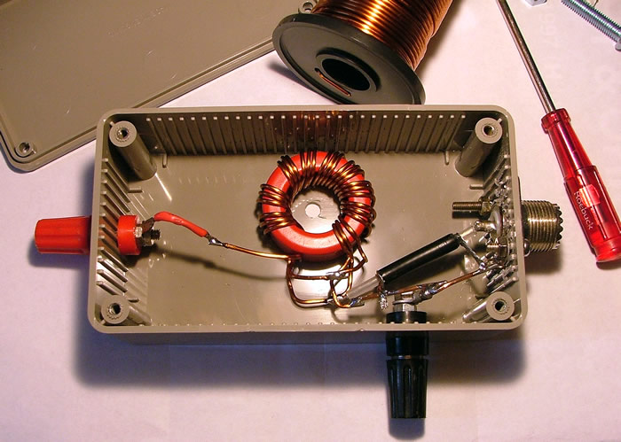
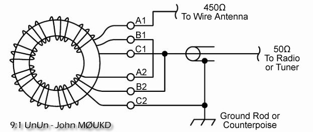
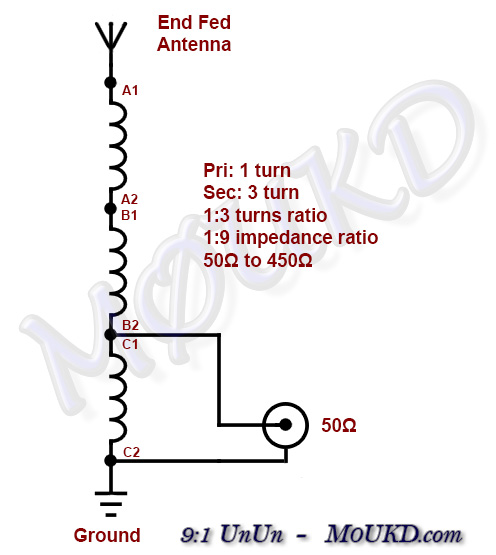
These are sometimes known as a Magnetic Longwire Balun. Its really an impedance transformer (9:1) to feed a high impedance, end fed (unbalanced) random wire which is likely to be a few hundred ohms, and transform it into something closer to a 50Ω (unbalanced) coaxial input, hence UnUn. It can however also be used as a balun by not grounding the other half of the balanced output. The toroid is a T130-2 Iron Powder core, with 3 x 9 turns of 18SWG enammeled copper wire, and the connections can be seen below.
M0UKD Amateur Radio Station Information Page © 2007-2017.


The common mistake is to call these things “balun/ununs” when in fact a balun and a unun are 2 totally seperate creatures. A balun is designed to match an unbalanced source to a balanced load thus the name – BAL/UN BALanced to UNbalanced. And a UNUN is designed to match an unbalanced source to and unbalanced load – UNbalanced to UNbalanced and what you show here is simply a UNUN. I was directed here by another ham that was confused by the term “BALUN/UNUN”. I know this is splitting hairs, but there are folks out there that are easily confused by such things.
Would you please share the approximate size of the box you used for your “Unun”?
Thanks
Dave Deitrick
KB8XG
Hi Dave.
Its approx 4″x2″ ish… Whatever the core fits in 🙂
Good luck!
VISITE MY HOMPAGE ON FACE -BOOK ;
https://www.facebook.com/TrocatrecoRadioamadoresPxEAfins
OTHERS HOMPAGE;
https://www.facebook.com/groups/229435297187443/
JOSE TRIJILLIO AMATEUR RADIO IS SWLISTENERS ,PY2-135 SWARL .
73´S
TRIJILLIO .
Hi John,
I love your website, loads of informative and helpful information.
I’ve made several MLB’s and some work better than others. I made one using a ferrite rod which works well, but I find that it’s acting like an aerial and picking up local interference which is added to the wanted signals.
My question is, will it degrade the performance if I place the ferrite rod in a dicast box and earth it.
Regards
Les
Hi Les.
Thanks for the comment. I have not heard of this happening. It should be OK to put it in a metal box though.
Good luck, John.
Can you use this with a moxon antenna?
Regards Steve M6SFU
Hi Steve.
No, a Moxon has a 50Ω impedance. If you wanted to use a balun on a Moxon antenna, I would suggest using a 1:1 choke balun.
Good luck! John.
hi what length should cut for each of the enameled wire.
just that i need to build a 9:1 for a long wire hoping to construct something for 160 mtrs-6 mtrs along my fence line which is 90`x 50` but if needed i could run wire up to my garage thus 50` more.
regards m1tvr mark
Hi Mark.
If you go to http://toroids.info/T130-2.php and select your toroid, enter the turns and press ‘calc’ and it will tell you the length you will need. I’d always add on 20cm or so to be sure 😉
Good luck with it! John.
Someone linked balun to antenna analyzer to see the frequency response. Because this toroid is suitable for resonant cirqles.from my experience I found that a suitable for baluns ис FTxxx-43 , J-material and similar.
Hi Krasi.
Yes, the iron powder torroids are not very broadband and don’t really provide enough inductance to do a good job as a multiband balun.
Is a magnetic UnUn the same as a 9:1 UnUn or are they totally different things?
Ian
2E0GXX
Hi Ian.
Yes it can be confusing! People tend to call these ‘magnetic longwire balun’ or similar. Almost all impedance transformers are magnetic, so yes they are the same. It just refers to the electromagnetic coupling between the primary and the secondary which allows for the impedance transformation.
Good luck & 73! John.
Hi John.
Do you have any information on how to make an MLB that can be used with 300 ohm open wire feeder instead of coax? I have severe interference problems within my flats, so I am trying to minimize any feeder pick-up by using a balanced system.
Regards
Les.
Hi Les.
I would recommend using a 1:1 choke balun for balanced feeder to ensure any common mode current is choked off and balanced currents are fed into the feeder.
Good luck! John.
Thank you John I’ll give it a go – I’ve been a SWL for 50 years and I can’t believe how much the interference level has increased in recent years.
I’ll try anything that might improve the S/N ratio, but I fear that I’m losing the battle.
73 John
Regards Les.
I built this for Field Day and it seemed to work well on my 70′ longwire with counterpoise.
73 de N8TUT Doug
Hi Mark.
To make this into a balun, I would connect the 50Ω side to B1 and B2. The 450Ω side would be A1 and C2.
Good luck! John.
Hi john:
If you connect B1 and B2 to the 50 ohm coax output it seems like you are putting a short
across B1 and B@. I am confused about converting this to a balun. The A1 C2 connections
are ok. Please help with the 50 ohm side configuration. I need the balun for my antenna.
Thank you,
Don, w9obq
Hi Don.
I can’t see why you think it would be a short. We are just moving up the 50ohm side from ground (from C1 & C2 to B1 & B2). This would however be a balanced to balanced transformer.
Good luck, John.
WILL THIS HANDLE 100 WATTS.
what is the difference between 9 winding’s and 10 ,? winding’s.
would it make a difference if i used 22 awg wire.
Hello OM,
I use an 4c65 white ferrite ringcore, thats realy better !!
73 de PD0MV
Par and the end fed half wave resonant antennas use a 64 to 1 transformer. So does my antennas.com.
Correct for an end fed half wave. For a random wire 9:1 is likely to get you in the ball park!
Les,Mfj 1026 and Timewave anc 4 are noise canceling units. Check eham.net /reviews
Is there any reason that the three wires could not be wrapped around each other (sort of like twisted pair cable) prior to being wound around the toriod? Since I do not see it done in any pictures, I am guessing it’s not a good idea…but it would make winding easier, I believe, so I thought I’d ask.
No reason why not, it would be good if using thinner wire.
I have 1:9 Balun. Can I make a HF transmitting dipole with 1:9 Balun? Kindly share the design. What should be the dimensions of both the arms of the dipole?
Will be grateful, if somebody also sends the dipole design with 1:9 balun to my email address:
vu2oec@gmail.com
73
Hi Rajesh.
I’m not sure what dipole would need a 1:9 transformer, unless it’s extremely offset fed!
73, John.
Why 3 windings?
and
Why 9 turns?
Please explain the impedance transformation taking place.
Andrew
Hi Andrew.
It is a 1:3 ratio. Impedance transformation is calculated by squaring the secondary turns ratio (note ratio, not actual turns) 3² is 9. 50×9=450Ω (our input impedance x 3²).
Hope that explains things. Cheers, John.
I try this unun using T130-6 toroid. Working well from 6 to 40 m (ocf dipole, 66″ long)
Best 73 de Nick, yo4lhr