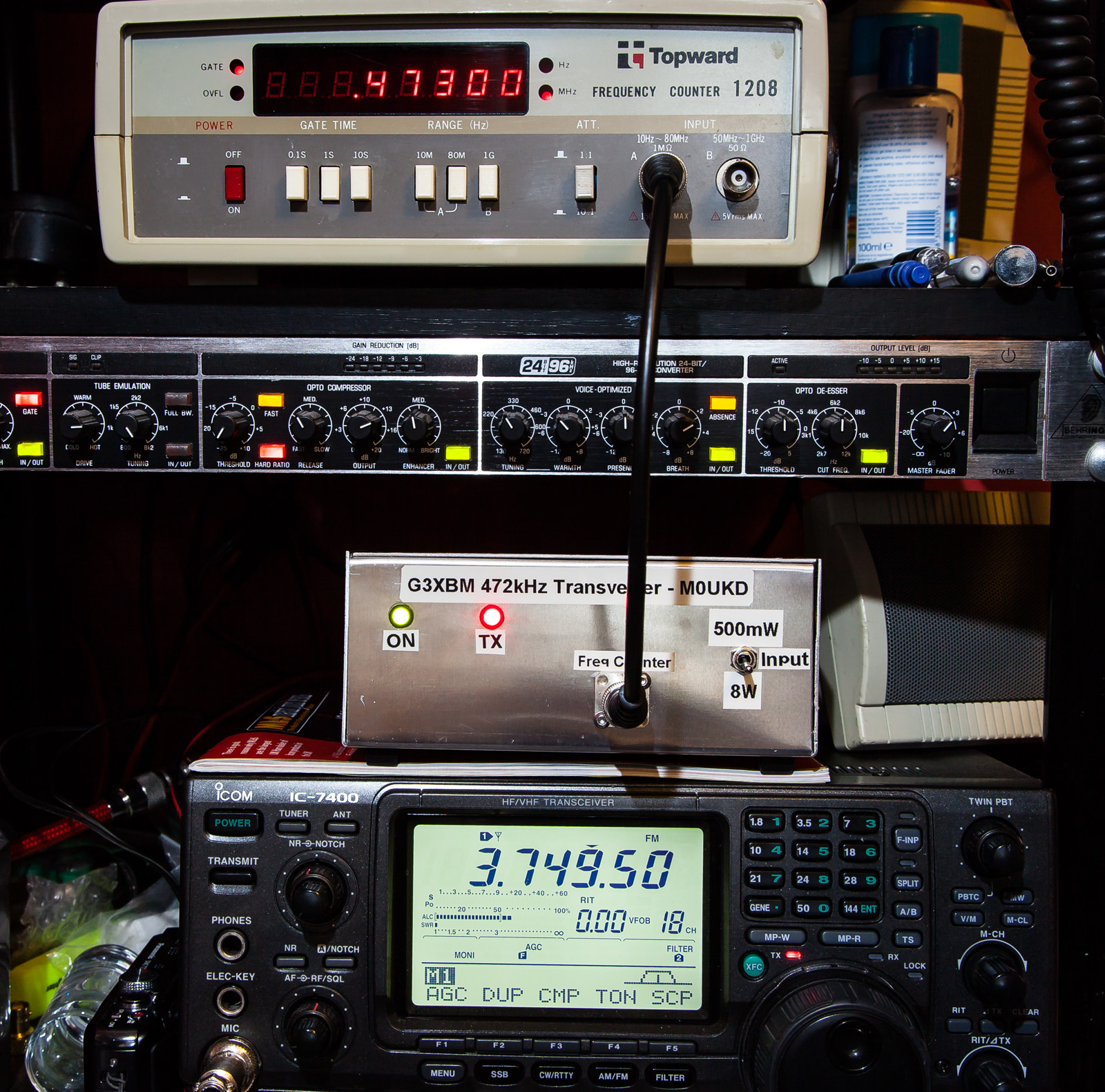
Here is my 472kHz 630m transverter. A design by Roger G3XBM. The schematic I built is here.
I added TX/RX switching, a switchable 12dB attenuator for 0.5w or 8w drive and an output via a 100pF capacitor for attaching a frequency counter.
The local oscillator uses a 3.2768MHz crystal, and is set to 3.2765MHz by a 5-65pF trimmer. The input frequency minus the local oscillator frequency determines the output frequency. An input of 3748.5kHz gives an output on 472kHz.
Output power is about 12w at 13.8v.
And the first QSO, George M1GEO on CW!
And the first few WSPR reports on an unmatched antenna! ERP must be microwatts..


Hi John,
very interesting project, do you also have an schema showing the modified version of the G3XBM transverter for 472 kHz? I’m particularly interested where to put in the connector for the frequency counter, since I think this is a great idea to have 😉 Also, what type of antenna are you using for 72 kHz operations for both WSPR and CW? Are you using an earth electrode antenna just like proposed by G3XBM?
Thanks for your help.
Cheers,
Max
Hi Max.
The connector for the frequency counter is just a tap off the output via a 100pf capacitor.
As for an antenna, I was just using my 20m doublet strapped and fed against ground via a homemade ATU. Seemed to do surprisingly well considering!
Good luck with yours, perhaps we can work on WSPR sometime!
73 John.
Where did you find your enclosure please ?
I have a VK3XDK transverter V2 and i would want a beautiful enlosure for it.
73 from Paris.
Hi Joe.
I bought this chassis from Maplin, an electronics retail store here in the UK. Its just bare aluminium and quite cheap.
Kind regards, John.