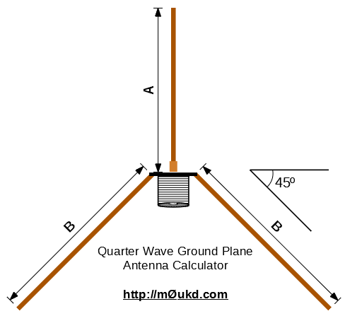
Ahh, the good old quarter wave ground plane! This calculator can be used to design a Quarter Wave Ground Plane antenna, with radials. The radiating element is a quarter wave (λ/4) and the radials are 12% longer. There are usually four radials, three being a minimum, but you could use up to six. This is a true unbalanced antenna, with a feed impedance of around 50Ω and therefore a great match to 50Ω unbalanced feedline. The velocity factor is set to 95% which should be fine for most people. You could cut a little on the large side and trim the antenna for best match at your desired frequency if you have the equipment.
These antennas can easily be built for UHF or above by using a chassis mount N-Type (or SO-239) connector, some solid wire and solder. For VHF and below, as the elements get bigger, some more structured design is needed.
A quarter wave monopole mounted against a perfect ground will have an impedance of around 36Ω but by bending the radials down at an angle of 45°, we increase this to around 50Ω whilst at the same time lowering the radiation angle more towards the horizon. (42° is the theoretical perfect angle for 50Ω feed, but who’s measuring!)
I have made quite a few of these antennas over the years with good results. They are very forgiving due to the low impedance feed. I use one at home on 70MHz, click here to see construction details and more images.
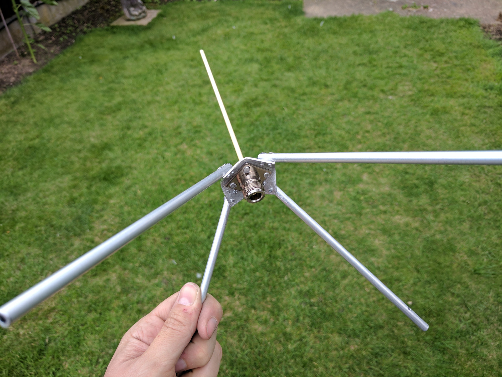
The next two images show one I built for the 70cm band. It is good for use between 430-440MHz. It uses 6mm aluminium tube for the radials, 4mm brass tube for the driven element and is built around an N-Type chassis socket mounted to a 40x40mm aluminium square, held together with rivets.

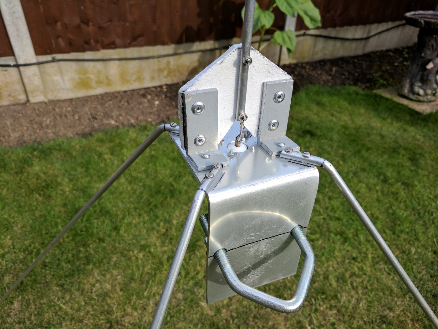
Below is some images of one I built using an SO-239 socket riveted to a piece of aluminium sheet, with telescopic elements. This means it can be used on any frequency between 80MHz and 410MHz (It’s a shame they don’t go a bit smaller and a bit larger, so it could cover 4m and 70cm, but they are what they are). It’s a good antenna for testing.
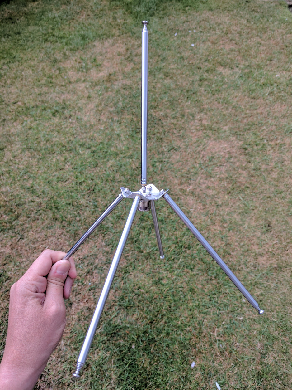
Here it is set up in the garden for testing on 145.500MHz

And, the impedance and reactance are perfect!

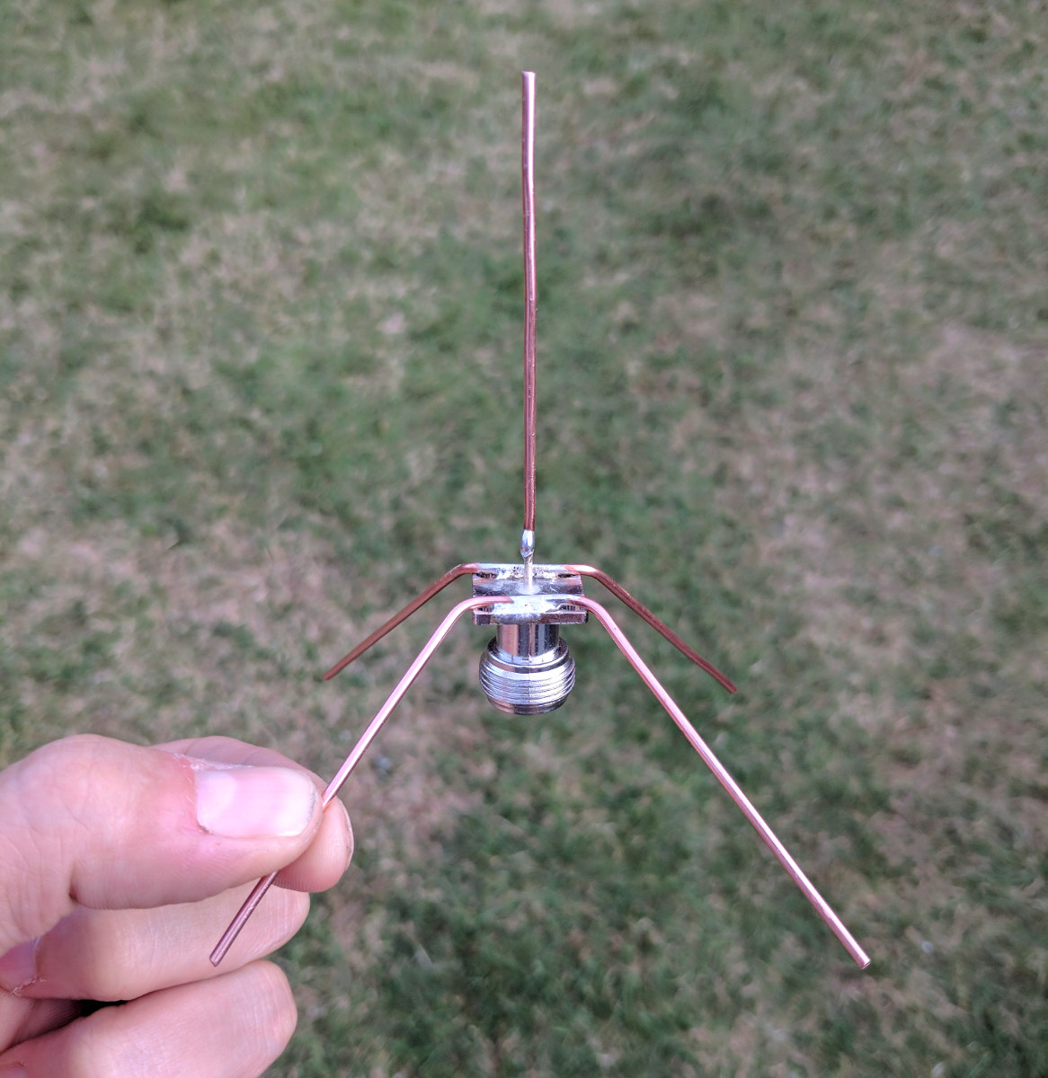
Below is a quarter wave ground plane antenna I made for 23cm, 1296MHz which is made from off-cuts of household mains copper wire and a scrap BNC socket from the junk box.
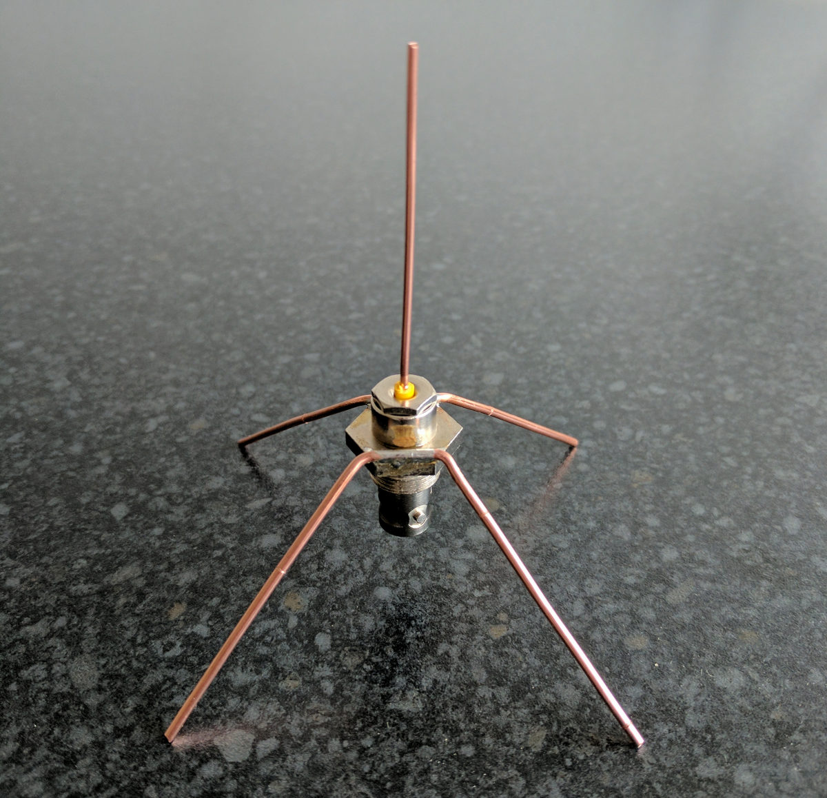
The one pictured below is for receiving ADS-B aircraft signals on 1090MHz, again using scrap copper, but this time a purchased N-Type chassis socket.