
I had a dipole up for 4m previously (see here), which worked fine, but was quite ugly on a 1 metre boom arm. I wanted to make something simple that would be reliable and not require a balun or any impedance transforming, so I decided to build a quarter wave ground plane antenna for home. The quarter wave is a good reliable antenna, and SWR is very robust and not affected by rain or snow etc. It can be built with very predictable results, even near trees or buildings, due to it’s low feed impedance.
They are easy to build, especially for the UHF bands as you can simply use a SO-239 or N-Type chassis mount. For VHF and below however, they require some more heavy duty construction. The trickiest part of course is mounting the driven element, whilst being insulated from the main mount.
I made a calculator that can be found here for working out the required lengths for the driven element and the radials. The final dimensions are 100.5cm for the driven element and 112.5cm for the radials (Velocity factor ended up 0.943 and centre frequency was 70.4MHz). The radial length is measured from the bottom of the driven element, so actual rod length is slightly shorter.
Construction started with a flat piece of aluminium sheet, which was cut slightly larger than the ‘U’ bolt that I was going to use, then bent into a right angle shape. This wasn’t easy, a blowtorch, vice and hammer was needed! The ‘U’ bolt and SO-239 chassis mount were then drilled and mounted.
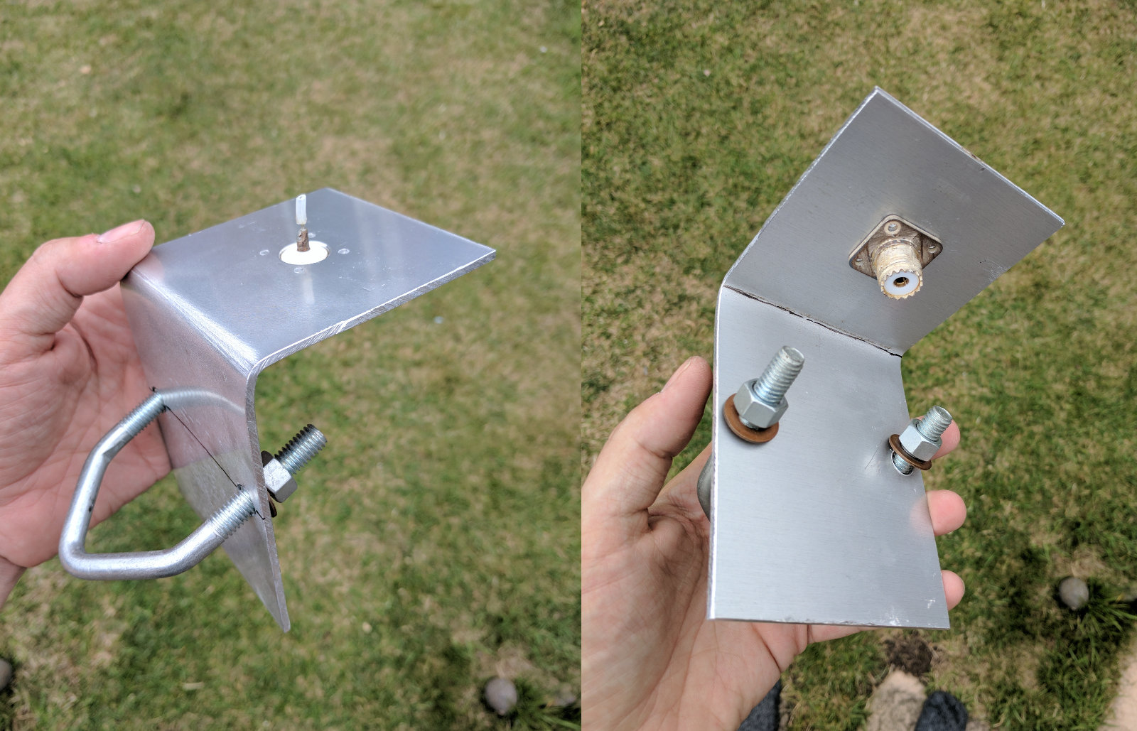
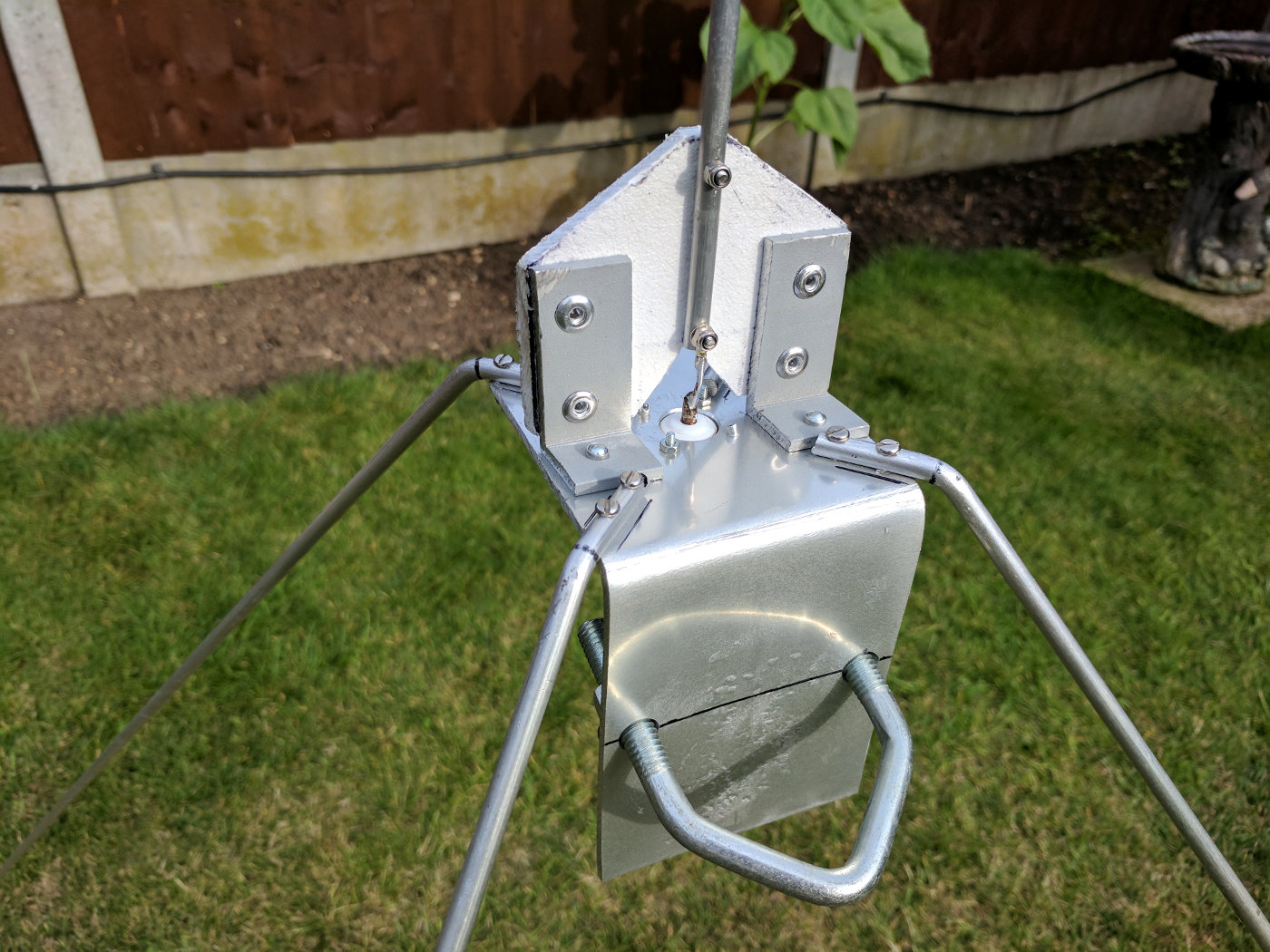
The main mounting structure.
The problem now was how to mount the radiating element rigidly, whilst being insulated from the main structure. I decided to use a chopping board (inspired by George M1GEO) for this task. So, taking the same width as the aluminium plate, a piece of chopping board was marked and cut to shape.
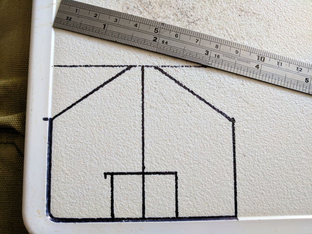
Making the insulated mount for the driven element.
Then, I cut two pieces of angled aluminium to mount the plastic to the base. These were mounted using 5mm rivets, then the driven element was mounted to the plastic and connected to the SO-239 chassis mount.
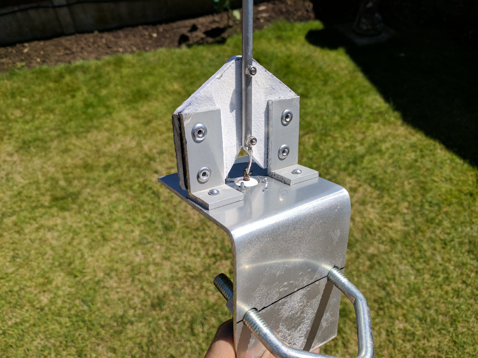
The mounted driven element.
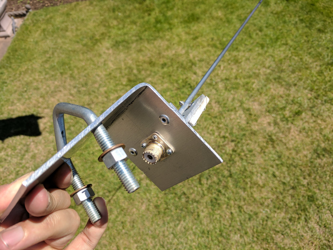
The 5mm rivets used to mount the driven element insulator and the feedpoint connector.
Next, I had to cut the four radials.

The four radials, bent at 135° cut and ready for mounting.
The radials were then drilled and bolted on, then the antenna was ready for testing.
The finished antenna, ready for testing.
The antenna was then raised above ground for some initial testing.
The antenna being tested in the garden.
SWR was good straight from the calculator, about 1.2:1 going to 1:1 at about 69MHz, so about 0.5cm was cut from the driven element and 1cm from all radials. This resulted in perfect resonance at 70.45MHz and a perfect match to 50Ω coaxial cable. Reverse engineering showed it to have a velocity factor of 94.3% (0.943 in the calculator).
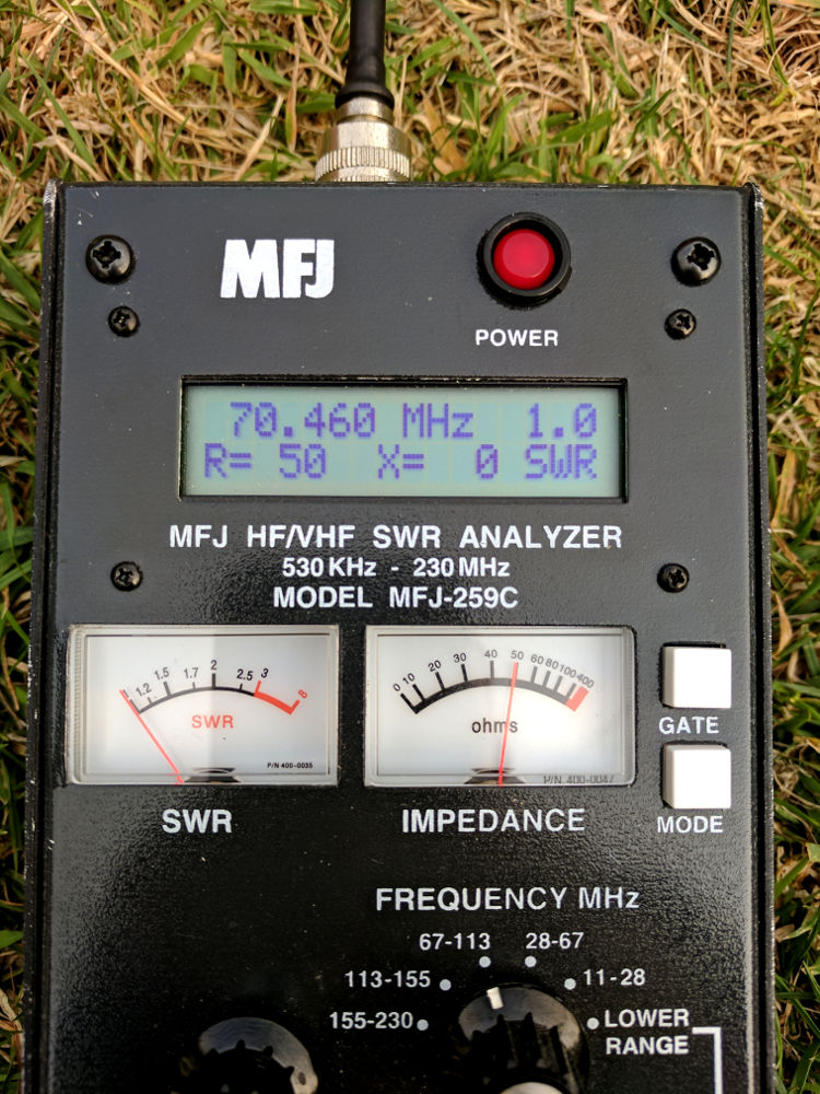
The perfect match and resonance on the MFJ-259C.
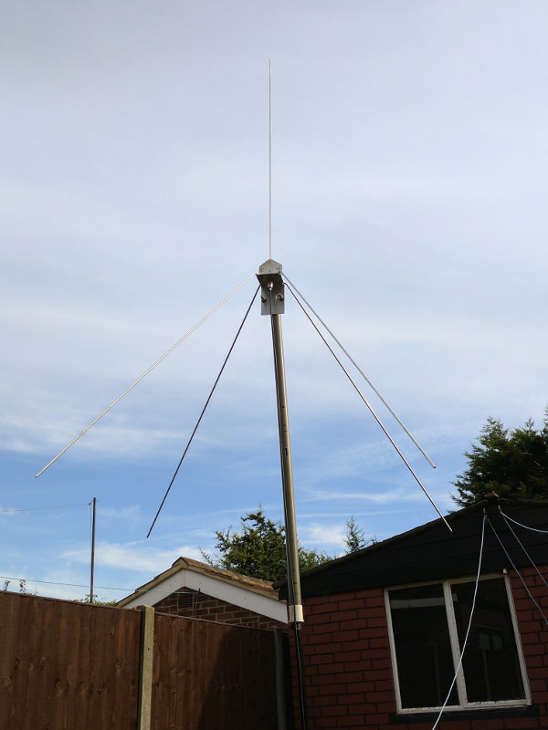
The antenna was then sealed with silicon where required and raised up in the air in it’s permanent position. SWR stayed good when tested in its final position.
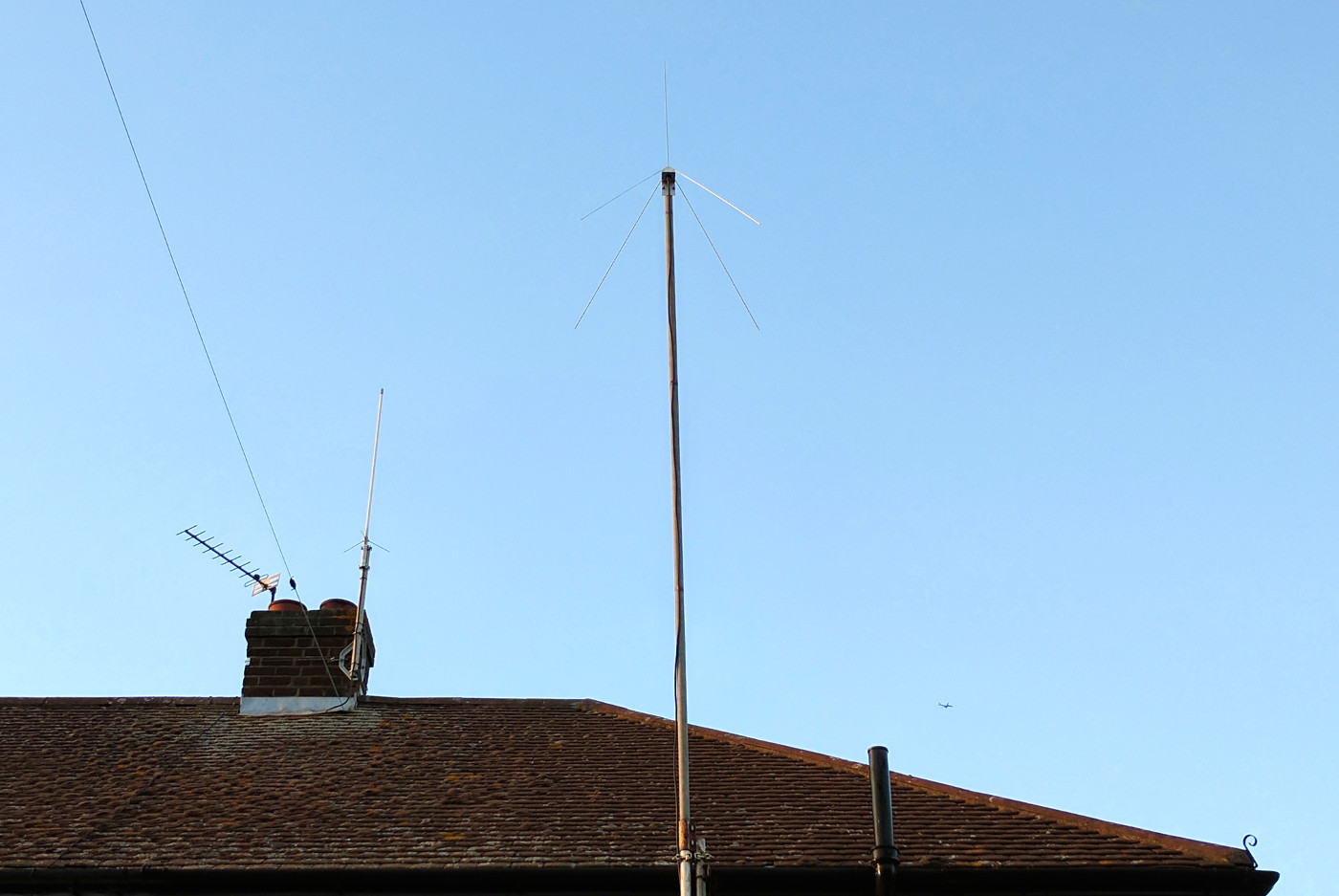
The 70MHz quarter wave ground plane antenna in it’s final position.
It’s good to be back on the 4m band. The antenna performs well and was fun to construct. It should give many years of service!
Good luck if you decide to build one and I hope to hear you on 70MHz 🙂