
Before we start, be prepared to experiment! The calculator will get you close (or spot on if you're lucky), but there are so many variables. You can use an antenna analyser to easily find if you are too long or short. Tuning can be done by adjusting the 1/4 wave stub length and the feedpoint position. To bring the resonant frequency up, shortern the 1/4 wave stub. To bring the resonant frequency down, lengthen the 1/4 wave stub. Bandwidth is much narrower than a centre fed dipole due to the tuned matching section, which makes building the antenna more critical. Tuning should be done out in the open and away from the ground, or the final mounting position if possible. OK, now thats out of the way, lets continue...
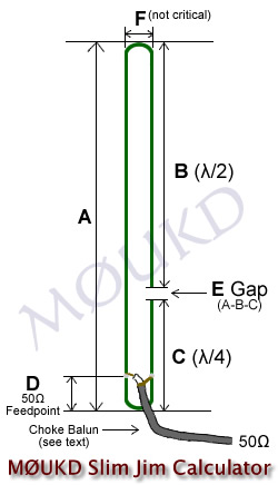
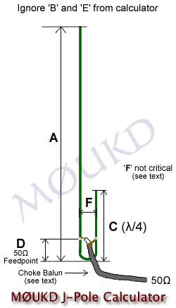
This calculator can be used to design a Slim Jim or a J Pole antenna. The Slim Jim, designed by the late Fred Judd, G2BCX, can be a great portable 'roll up' antenna, if made out of 300Ω or 450Ω ladder line / twin feeder. Add a loop of string to the top, and hang it on a tree branch, use it with your handheld transceiver, then roll it up and put it in your pocket when done! A Slim Jim for 2m (145MHz) will be 1.5 metres long, and 70cm (433MHz) will be 0.5 metres. Alternatively, for permanent installations, the copper tube or aluminium J-pole is a good choice. I have had good success with both, but regularly use the balanced feeder Slim Jim mounted on a 9m fibreglass pole, as can be seen in the photo at the bottom of the page.
It is recommended to use some sort of choke at the feedpoint. Three turns (for 145MHz) of the coaxial cable around a 40mm former (PVC pipe etc), or taped up and hung freely is adequate. Five turns, 6cm diameter for 70MHz. I have also used a clip on ferrite or two for VHF. As with any balanced feed antenna, this will help prevent the braid of the coaxial cable from radiating, and becoming part of the antenna, and therefore affecting SWR and performance. You can check the effectiveness of the choke by touching the coax below the choke and if the SWR changes significantly, your choke is inadequate.
The spacing between elements, I have shown as 45mm on 2 metres. This is not critical. It will have some effect on where the 50Ω feed point is, but i'm sure you'll find it! The critical lengths are B, C, and E then adjust the feedpoint to find a perfect match. Ignore B and E if building the "J pole". All dimensions should be between the closest metal to metal (inside), not centre to centre. a 1.0:1 SWR will be possible when the antenna is working perfectly. If you cant get it perfect, the length of the elements may need adjusting or the choke is not adequate. Just remember, when adjusting elements, 1cm shorter on 'C' would equal 3cm shorter off 'A'!
*Velocity Factor: I have added the ability to select the velocity factor of your conductor. It is set by default to 0.96, which is for bare copper or bare aluminium. If you use balanced feeder such as 300Ω or 450Ω, adjust it to 0.9 (or set to the cable manufacturers specification if available). The diameter of the elements will also slightly affect the length.
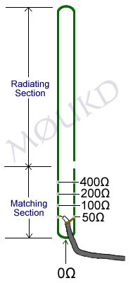
50Ω feed point: The 50Ω feed point is a starting point and should be adjusted up and down until you get a 1.0:1 SWR (or as close as possible) with your antenna. You could even use a 4:1 coax balun and feed it higher up the matching section. If you can't find the 1:1 point, the elements are either too long or too short. This is where an analyser comes in handy. Tuning can be done by adjusting the length of the 1/4 wave stub 'C'.
I made one for 4m (70MHz) which is 3 metres long. The quarter wave matching section can be made horizontal, with the half wave radiator section vertical, 90° to it if space is an issue, although this will affect radiation pattern slightly. Just remember the whole antenna needs to be in the clear, away from any objects, especially conductive objects!
So, how does this thing work?
The Slim Jim, similar to the J-pole, is in fact a half wave end fed dipole, in the Slim Jim's case, an end fed folded dipole. As with all folded dipoles, the currents in each leg are in phase, but in the matching stub they in phase opposition, so little or no radiation occurs from the matching section. You may think how can you say this is a dipole, when its just one element? Well, contrary to popular belief, the dipole is so named because it has two electrical poles, not two physical poles. Wouldn't that be a di-element!? Just like a magnet has two magnetic poles, a North and a South, we have two electrical poles, a Positive and a Negative. Being a half wave, there is always two opposite poles on the tips at each half cycle. Any half wave antenna is actually a dipole.
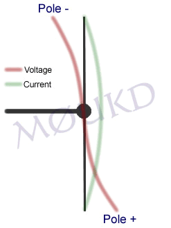
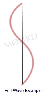
To help explain this, I have drawn above what happens to the voltage on a half wave element during one cycle. You can see, there are 2 poles, one positive and one negative at each half cycle. Hence, 'dipole'. As its a half wave element, the wave is opposite at each end. Unlike the full wave example on the right, where the wave will join up if you imagine placing it on top of itself.
Hopefully, this explains things, and shows that the Slim Jim is actually a half wave dipole. A dipole, is usually fed from the centre, where the impedance is about 70Ω. This provides a reasonable match to 50Ω coaxial cable, and is why the centre fed dipole is so widely used. A dipole can be fed anywhere along its radiator, for example, the windom is 'off centre' fed at the 200Ω point, and an end fed half wave will give a very high impedance of up to around 5000Ω.
So, we are feeding this half wave antenna from a high impedance point, which needs to be matched to 50Ω coaxial cable, and is where the 'J Integrated Matching' (JIM) quarter wave matching section (λ/4) comes in. With the Slim Jim, you have the option to select the exact impedance you want, typically 50Ω. With the centre fed dipole, you have an impedance of around 70Ω.

The matching section is just a matching section and does not radiate significantly. The 'equal' but opposite currents can be seen in the EZNEC model of the J Pole above, however, as one end of the matching section is not connected, it will have an infinite impedance. The other end of the matching section is connected to our radiator and although this is a high impedance point, it is not infinite, which is why some slight radiation of the matching section is inevitable. The more perfect the antenna is operating, the less this will be an issue as we will have the highest possible impedance at the base of the λ/2 radiating section if it is a perfect half wave.
The 50Ω point can be found once you have built the antenna to the correct dimensions. Have the antenna out in the open, then move the feedpoint up and down small amounts, and when a 1:1 SWR is found, fix them there. An example of what the different impedance points may look like are shown on the image to the left. The calculator above will give you a good starting point, although spacing between the elements, velocity factor and other differences will have an effect on where this actually is.
Slim Jim vs J Pole
There are many rumours on the Internet, claiming that the Slim Jim has better performance than the J Pole. Simulation (and common sense) suggests that they are practically identical. John Huggins KX40 covers this question on this page. It is likely that any real world tests that show the Slim Jim to have better low angle gain than the J Pole is due to the (sometimes) poor way people tend to mount the J Pole by grounding the base to a mast or not choking the feedpont, as opposed to the Slim Jim usually being mounted freely. I build my J Pole antennas as a J and mount them insulated from any mast.
Here is a working 4m Slim Jim constructed out of 450Ω feeder, the stuff with the solid core. I have built two of these and it should be easily reproducible and work 'straight out of the box'!

Click image for larger version.
Dave M0TAZ using a 450Ω feeder Slim Jim on 70MHz.
Below is a J Pole that I built for 70cm. SWR is <1.5:1 from 430MHz to 440MHz.

I hope this has been of help to you. If you decide to build any of these, I'd like to know what you think of it and how you got on. Please leave a comment! Thanks, 73 John.
Hi
I just wanted to say a quick thanks for the article.
I got my foundation license last month and after reading this I just had to give the J Pole a go.
I got around 1:1.2 SWR without tuning which it is a good start and as good as a commercial dual band aerial I got over the counter.
Regards
Martin
M6GUP
Hi Martin.
Congratulations on getting your foundation licence! Good job with the J-Pole too!
73, John.
Have you had any feedback from hams that built this for 14.2 Mhz or 28 Mhz.
Thank You
No, but I would love to see one for 14MHz!
Cheers, John.
Thanks for the fantastic calculator John! I just built myself a J-pole from scrap pipe, and it tunes up beautifully across the entire (US) 2M band. Worked a repeater 50+ miles away on 7 watts.
There’s a YouTube video detailing the construction:
https://www.youtube.com/watch?v=cLqCtzqeQzI
The clothes pin Yagi Uda is next!
Cheers,
Matt – N3NWV
Nice one Matt! I’ll have a look at the videos. Good luck with the PegTenna!
73, John.
Hi,
You mention that “Just remember, when adjusting elements, 1cm shorter on ‘C’ would equal 3cm shorter off ‘A’” but at the same time state that tuning is done “by adjusting the length of the 1/4 wave stub ‘C”. So if one needs to adjust the length C for tuning purposes, must the length ‘A’ also be adjusted (by a reciprocal threefold amount)? You also state “Just remember the whole antenna needs to be in the clear, away from any objects, especially conductive objects!” – what about the trunk of a tree? – Would that be considered “conductive” and/or be detrimental to the antenna’s performance? I am planning to build one for 28,5 Mhz. (Given the solar cycle… no hurry!).
Hi Peter.
The calculator will get you close. For easiest tuning, adjust the 1/4 wave stub and the feedpoint height. Between them, this should be enough to reach 1:1 SWR. In answer to your question, no. A should be close enough with the calculator. I would only adjust A if you were having problems.
A tree would affect performance, but it should be OK. Give it a go! You might find when it rains, SWR changes a bit, due to wet branches and leaves etc.
I have not tried one on 28MHz, but would like to know how you get on!
Good luck! John.
what abuot the gain of the antenna .. and how it measure ??
Gain will be around 2.15dBi, same as a centre fed half wave.
Dear John,
I was wondering if you had a 75Ω coaxial version of your calculator?
50Ω feed point. Adjust for 1:1 SWR. to be (λ/40)*vf
But for 75Ω (λ/ ?? )*vf
Thanks!
Hi Philippe.
No, but it will be very close to the 50Ω point.
Good luck, John.
hi m0ukd,
we (few of us from Hyderabad,India) tried to make the slim-jim antennae for 145.0MHz. In specific, we tried using 14swg single strand copper wire.on 1″ pvc water pipe. The feed point i tried at 10cm it worked reasonable but swr was not optimum. another case, we tried at 5cm , SWR was fine , but antenna reception was rather bad.
Earlier your calculator was showing 10.3cm for terminating RG-58/u. Later as per one of your replies, you had modified the calculator and it shows 5cm now. the formula used by you (Lamda/40)*V.f works out to 5 cm only. but we could not optimize the antenna.
could you show little more thought with using bare 14 swg wire, please !
regards
sarma
(a retired telecom engineer )
vu3zmv
Hi Sarma.
Unfortunately, with differing conductors, placed near plastic or in tubing etc., it is hard to calculate. The calculator is optimised for 15mm copper at 145MHz. Experimenting and (hopefully) finding a good resonant match may be the only way I’m afraid.
Good luck! John.
I built the Slim Jim 450 ohm line for a friend. Got 1:1 SWR from 144-147.
Tried with a repeater 64 km away with 5 watts. Excellent!!!
Now I am going to build one for myself for VHF and UHF to replace my old J pole.
Thanks.
73′
Dubi
Hi Dubi.
Glad your build went well, thanks for the update!
73, John.
I love your J Pole calculator. It would be helpful if you offered a measurement selection of Metric or Decimal measurements. It would certainly be helpful to those of us in the US and other countries that use Decimal system. Thanks and 73’s…Phil…W2AR
OK Thanks for the suggestion. I might amend the calculator at some point.
Cheers, John.
Slim Jim a nice antenna for 2 meters band, may I have that caculator for Slim Jim antenna…?, just send to sambolang64@gmail.com Thank’s.
Samsul Arifin Muhammed ( SAM )
JZ10WSA / Indonesia.
Sorry, this one is JavaScript.
Hi Mike,
I have just run the calculator at 315 Mhz. for a remote gate opener. The provided antenna is just a piece of wire which gave me coverage of about 50 meters. I did replace it with a magnetic whip at about 1.8 meters high and it gives me about 100 meters. I will now redo it with the receiver built into the plastic water proof box right at the feed point and mounted at about 3 meters high.
I will report back on results.
Lee VK3PK
Would it work as well if a SO-239 were soldered on instead of the coax directly?
Yes, should be fine.
That full wave dipole antenna example shows current not voltage. Just to notify…
John, so helpful and amateur oriented way. TNX, here in my country (YV) many RG-6, RG-59, RG-11 catv/sat surplus coax with double braid and quality insulation, (better velocity factor) wonder if possible to tweak your calc to use it? by other side too expensive and not avalaible good 50 ohm coax. 73:51
Hi Carlos.
Yes it would be fine to use 75 ohm coax, ideally you would match it to 50 ohm at the radio end, if you have a 50 ohm transceiver that is!
Good luck, John.
I am new to ham radio this time around. When I left for life, college and military, SSB was new and FM was rare. So with new license on the wall I used the calculator to build a 6 Meter J Pole from .55 copper pipe. Beautiful to the eye. Got it in the air and on the air in time for a local 6 meter net. I could hear the moderator and lots of attendees but I could not join the net. In the middle of the night I realized everyone was using horizontally polarized antennas and mine was vertical! Now I see a J Pole might not be the best antenna for horizontal polarization on that band.
turn it sideways. it will work.
Estimado John:
Siguiendo su calculo de la pagina en JavaScript arme la J Pole para 28 mhz.
La antena es caño de aluminio. Esteticamente es un poco grande pero no mas que la antena BC 3 que tenia en uso. No tuve problemas de calibración y siguiendo las medidas obtuve una ROE de 1:1 para la frecuencia calculada (EXCELENTE). La verdad que promete mucho ya que en comparación con mi antena anterior obtuve mas sensibilidad en recepción RX y mejore mis comunicados en DX con mi Ranger RCI-2950 de 6 Watt en AM.
Le dejo mi saludo y cualquier duda le estaré concultando.
Soy Leonel de la Rep. Argentina Pcia de Santa fe.
73, Un abrazo.
Hi, and thanks for the calculator and the instructions.
I am trying to make a 450mhz antenne to use in order to improve the signal from my internet provider that broadcast 3g over the 450mhz band.
Lately they actually started to broadcast 4g as well on higher frequencies. Since I dont have a direct view and live about 22km from the transmitter, I was thinking that my chances are better with the low frequencies.
I have made a Slim-Jim that is ready for testing after tomorrow. I dont have equipment (or the knowledge) for tuning the antenna, so I guess the antenna will be as it is.
I have made it according to the measurements from the calculator above, but I was using a 6.5mm copper pipe. Bending this pipe resulting in the ‘F’ getting 3.2cm instead of 1.4cm. However this is said not to be critical, but it could have an impact on where the feeding point should be.
But I didnt find any information telling if the feeding point ‘D’ should increase or decrease when increasing ‘F’.
You mention that the calculator is optimized for 15mm pipe. But do you use the outer measurements for the lenght, inner or center?
For spacing I guess it must be inner measurements, since its impossible to get 14mm spacing between the center of two 15mm pipes anyway.
Also there mention of using a choke, 3 coils for 145mhz. But is any choke recommended for 450mhz?
regards, amyren
Hi Amyren.
Wow, interesting application. Yes, the measurements should be from the inside, the shortest path for current to flow. A choke is not essential, so I would omit it in your case.
Good luck!
Dear Friend, so good your comments and the calculator!
The idea of insert a j-pole in the box, is the must!!!!
TNX !!! 73’s
Fernando
PY2EPL
hey John Moukd.
calculator and hint of a nice slim jim antenna, really helped me. I made from 9 mm aluminum pipe with size and shape according to calculation, make measurements on 1: 1.1 swr meter and have a further range. I am very happy once again, thank you. and success is always for you, John.good lock form indonesia.
Curious what the effect on dimensions for using 22.22mm Copper Tubing?
I remember seeing an on-line calculator that took element diameter into effect. The Slim Jim I am working on is for 50.1Mhz.
Thanks,
Gary Johnson
K0GWA
Hi Gary.
Yes, velocity factor and bandwidth change with dimension of element. I would not worry for 22mm tube, it should work fine. I built one for 70MHz with 15mm tube, it was a bit heavy, so yours will be even heavier 🙂
Good luck with your build. 73, John.
Thanks John, I designed for 50.1mhz about 14′ overall, hope to have it finished today.
Thanks for the nice tool.
Gary