
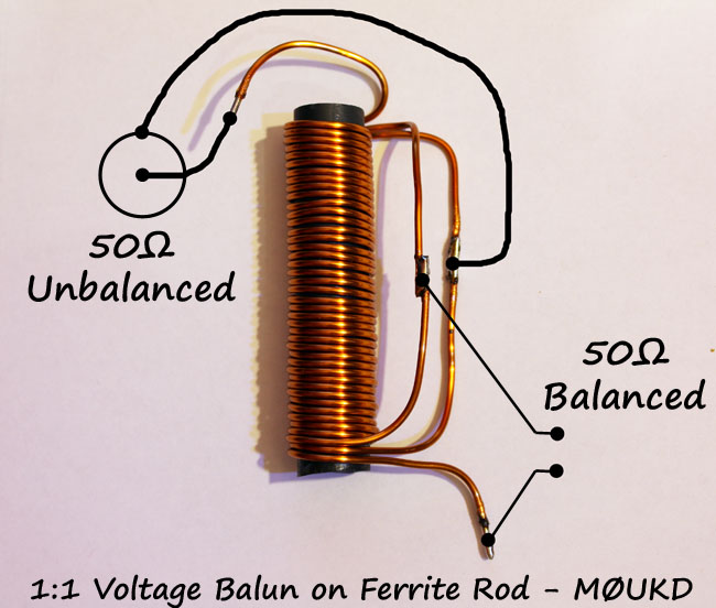
Heres a neat 1:1 50 ohm balun for use on HF horizontal wire dipoles. It uses an AM radio ferrite rod, with 3×14 turns of wire. 10-14 turns should be good for 2-30MHz. I used 18SWG enammeled copper wire. It all fits in a small project box. Great for setting up portable. For 20 metres, I started with 6 metres of wire per element, and trimmed each down until it has minimum S.W.R. I managed to get a 1:1.1 S.W.R. on my desired frequency. Bandwidth from the resonant frequency is about 200KHz either way, any more needs an ATU. The wire and ferrite core I had already, the box, terminal plugs and SO-239 came to about £6. The balun can also be built on a ferrite toroid such as an FT140-43 or FT240-43.
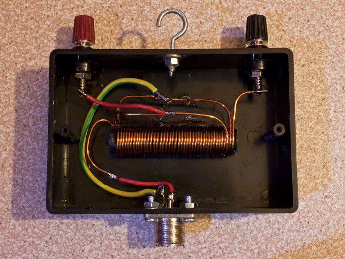
1:1 ferrite rod voltage balun
Bandwidth may be increased by more spacing between each trifilar turn. I didn’t have room on this tiny ferrite rod, but it performs OK.
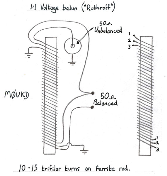
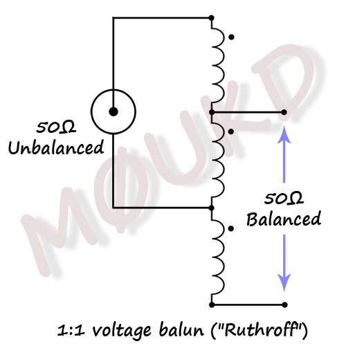
Schematic Diagram
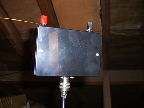
This is it wired up to my loft dipole
Hello John,
Can u tell me the lenght off the 2 wires for this 1:1 balun, thanks end hope to speak whit u on the HF bands.
Hi Rene.
Sorry, I don’t know the length. They are as long as they need to be, that’s all I know 😉
Good luck, John.
TRIFILAR COIL ON RODE FERITE
12 MM FERITE RODE ONE TURN IS 3.5 TO 4 CM METRIC SYSTEM I USE
SO IF NEED 14 TURNS 15 TURNS * 4 CM = 60 CM PER COIL * 3 = 180 CM OR 1 METER 80CM OF COPER WIRE
AND IF YOU HAVE ANTENNA ANALYZER PUT A RESISTOR 50 OHM FOR 1 TO 1 BALUN OR 200 OHM FOR 1 TO 4 BALUN IN DIPOLE SIDE AND MAKE YOUR MEASURES FOR SMALL SWR NUMBER IN DESIRED METER BAND.
AND CUT IN THE LITTLE COPER WIRE THE TIME OF TEST.
Hi John.
First thank you for publishing this. I just last night took apart an old Hygain balun meant to be used with a beam’s driven element, or with a dipole with a center on a pole, and was puzzled by the ferrite rod and what appeared to be trifilar winding.
So two questions (I’m an old EE but I’m still occasionally thrown by RF transformer practical considerations) 1) why does the winding have to be bifilar or trifilar, instead of a 14 turn winding with each end on the SO239, and another 14turn winding with each end to the dipole halves?, and 2) would not a toroid, which does not rely on air to complete the magnetic circuit, be a more efficient (less lossy) core configuration than a rod?
Hope you can help me on these two. I actually made a 35t:7turn 5:1 (Z ratio 25:1) rf transformer with the primary to an SO239 and a secondary electrically isolated from it to an 80m OCFDipole and it worked well after I shortened it. Configuration and material were T140-43 from Amidon. But I had to shorten the 80m dipole from 132′ to about 125′ (119 on one side and 6.5′ on the other) to make it go 1:1 and someone said it might be that the windings for primary and secondary have to be “intersticed” with each other. I would think that would introduce stray capacitance. All instruction or instructional links appreciated if you have the time. Best. Mike.
Hi Mike.
Firstly, I’m no expert 🙂 I have found a ferrite rod or ferrite toroid to work well as a voltage balun. A voltage balun needs to be trifilar. Yes, there’s no reason why you can’t use a choke balun, although if you are matching a 50r load to a 50r feed to a true balanced antenna, I would prefer to use a voltage balun.
An OCFD is obviously not balanced, so it’s hard to know whats going on if you feed it via a voltage balun, but I suspect it can’t be good, unless theres somewhere else for the current to go on the short side, like the vertical section in a ‘Carolina Windom’.
Good luck with your tests, that’s what its all about 😉
73, John.
I followed your instructions and the connected the balun to a 40 meter dipole. I can tune 200 khz at less than 1.5 : 1 swr. Thanks for putting this link online. 73 Jim
Voltage baluns always try to force the output terminals to equal voltages. They sometimes introduce phase shift between each output terminal and “ground”. If the impedance presented at each terminal is not exactly equal, feedline or load currents will not be equal and opposite. This means the feedline will radiate.
They also do not provide common-mode isolation. A voltage balun almost certainly guarantees some feedline radiation (or reception), because there are very few “perfectly balanced” loads or perfect voltage baluns.
Unlike a 1:1 ratio current balun, a voltage balun will always magnetize its core in direct proportion to load voltages. In a voltage balun, load impedance directly affects core heating and flux density.
Current baluns, rather than voltage baluns, should be used whenever possible. Current baluns provide better balance and often have lower loss. Current baluns, especially 1:1 ratio baluns, tolerate load impedance and balance variations much better than voltage baluns. Current baluns can also be used as isolators or un-un’s.
hello mike
I would like to ask you if the oven heats up ?
Very useful info. Thank you.73