
Following on from the simple CW touch keys in the previous page, this page shows a capacitive touch project which is the ideal touch sensitive key solution. The project described here is a iambic capacitive touch key which uses 2 AA size batteries for 3v power, draws <1mA current and has an ‘on’ switching resistance of <0.1Ω with a 3v supply.
The circuit diagram schematic is shown below.
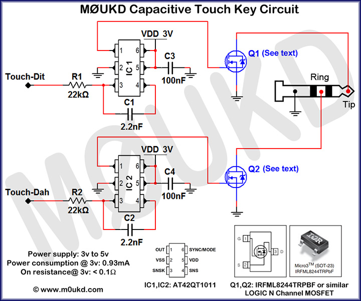
Figure 1: Capacitive touch key circuit. Data sheets: AT42QT1011 | IRFML8244TRPbF
The circuit in figure 1 uses all surface mount (SMD) components. One reason for this is that the IC is only available in surface mount, but the reason for the use of SMD for the whole circuit follows:
|
When designing this circuit, I was going to power it with a 9v PP3 battery, through a 7805 5v regulator. This would have allowed the use of many logic level MOSFET’s, of which I was going to use the 2N7000 which has a TO-92 case. The problem with 5v supply to the AT42QT1011 is that at 5v, they draw around 1mA each. Add on the losses involved because of the 7805 regulator and overall, its just not ideal for power consumption. A transistor could have been used, but I prefer the use of a MOSFET to keep the circuit power consumption to a minimum and it saves adding a base resistor into the design. Also, there’s just something about MOSFET’s, isn’t there? Oh, maybe that’s just me!I did some tests at varying voltages for the current draw of both devices together plus the on resistance of the MOSFET at the corresponding supply voltages and the results can be seen in the table on the left. I decided that 3v would be a good supply voltage, which is easily obtained by two AA or AAA batteries, and the circuit would draw just under 1mA. The regulator would then not be needed and the battery capacity with AA’s would be much more than the 9v PP3. This means that the battery life using alkaline AA’s in this circuit is well over 3000 hours. Of course, you could use a 7805 5v regulator and power this from your 13.8v supply instead of using batteries if you didn’t plan on moving it around too much. |
The problem with using 3v is choosing a MOSFET with a low enough gate threshold voltage. Whilst searching for suitable MOSFET’s, it became clear there was no good candidate which was not SMD. Its a fact nowadays that SMD components offer much greater choice over their through-hole ancestors.
The MOSFET that I chose was the IRFML8244TRPbF which has a typical gate threshold voltage of 1.7v and a very low on resistance and comes in a SOT-23 SMD package. It was therefore decided to design the whole circuit around SMD parts. Many other logic MOSFET’s will work ok in this circuit, such as the IRL540, which comes in a TO-220 package and will switch up to 28A!
So, I had designed the circuit, tested the circuit, all that was left was to design the SMD circuit board, which I did with Eagle. The testing board I etched with photo resist PCB and developer. It worked fine and looked OK, but I decided as I had put the effort in to designing a board for this project, I would get some PCB’s professionally manufactured. The final design can be seen below. The PCB dimensions are 57mm x 37mm.
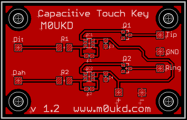
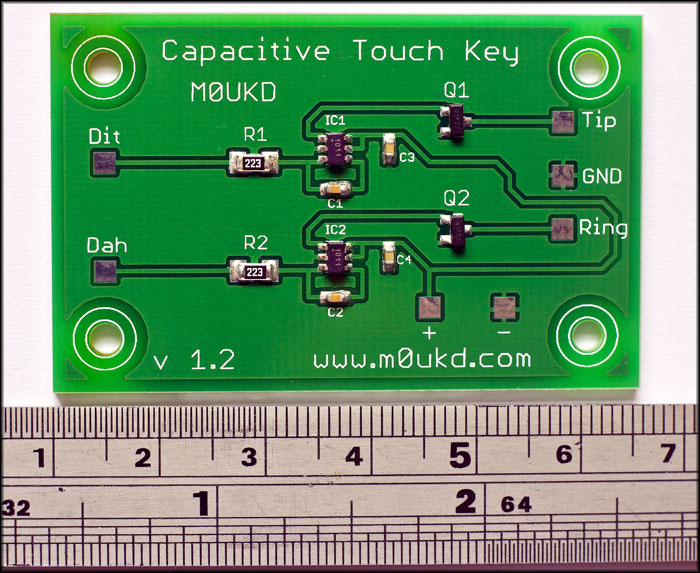
The completed board.
If you would like to photo etch a board yourself, a mirrored PDF file can be downloaded here. I have no boards left for sale at the moment.
Below is a video of how to solder the board using solder flux and hot air.
Below are some photos from people who have made keys with this board…
Built by Chris, M5LRO
Will, PA3Q
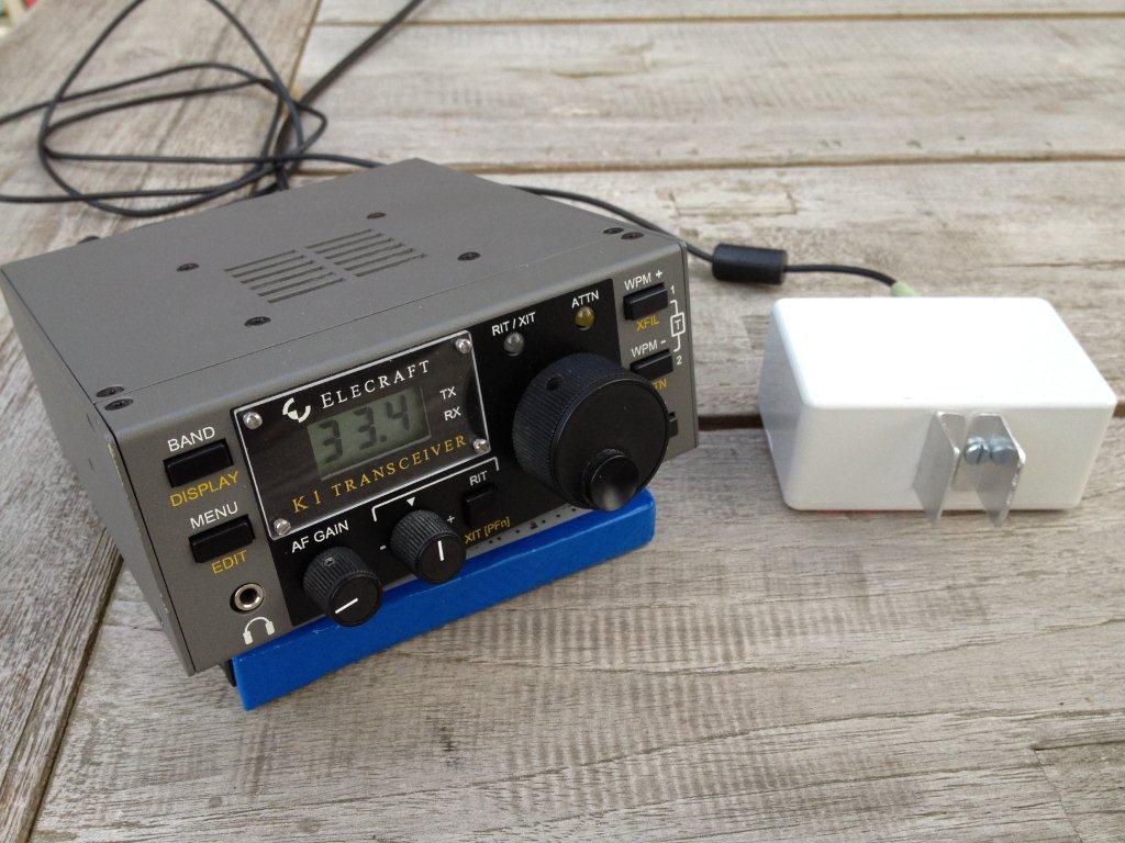
Wil PA3Q and his Elecraft K1
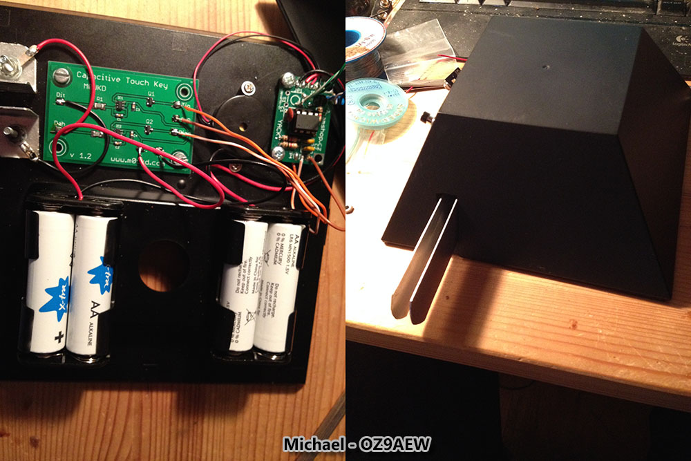
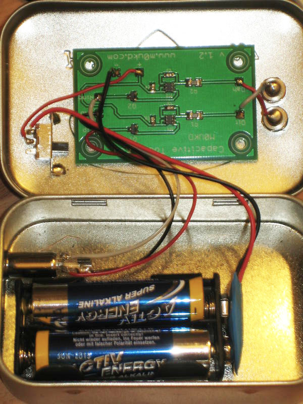
Michael OZ9AEW built his from a HTC cellphone box!
Below is a video from Stefano, IK5XCT who built the key. An interesting story is that as he says on the YouTube page, he had a contact using the key with DK7FH, who was also using one! Thanks Stefano!
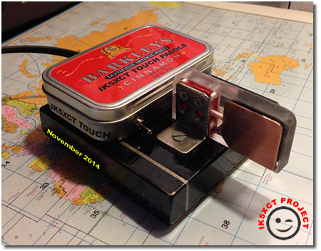
Stefano’s key
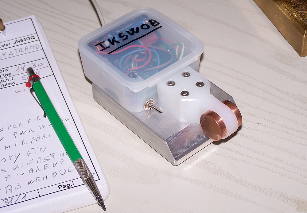
IK5WOB Fabrizio made an interesting looking key!
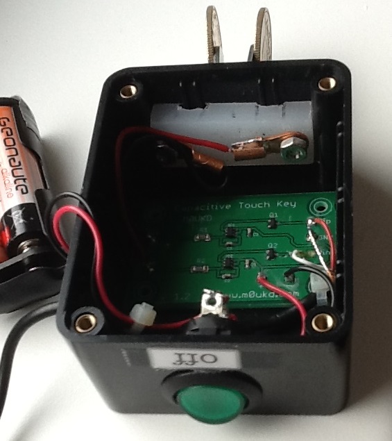
Frank DK7FH built it in a small steel container. He has some more QRP projects on his QRZ.com page.
Istvan HA5CLF made a nice small portable key
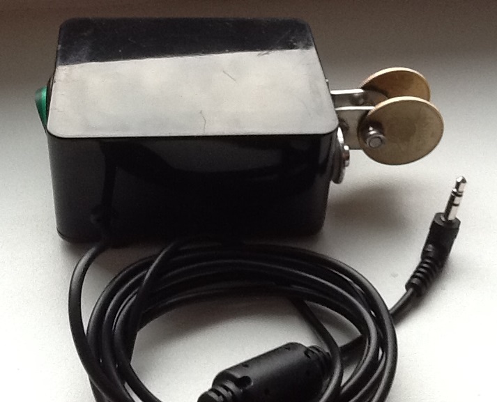
Istvan HA5CLF spent some money on his paddles! He used two coins for touch surface. They are 20 Ft each = 0.05 GBP!
If you decide to build any of the circuits listed on this page, I would be interested to know how you got on. Please drop me an email by going to the contact page. 73 de MØUKD.
Hi John
I`ve biuld my own version and it works nicely.
Thank you for share your Project.
Rgds
Hi John,
What are the possibilities and price incl. shipping to PA
Bare board?
Bare board plus components?
Fully assembled?
73, Rene
Hi René.
I have none at the moment, no boards or components. If I get some more I’ll let you know.
Kind regards, John.
Hi John,
Would you have the PCB only available?
Regards,
Gerben – PG5M
Hi Gerben.
Sorry, I have none at the moment. I’ll let you know if/when I get some more.
Regards, John.
Hi John,
came here via drew_k9qv who build for himself a capacitive keyer like yours. I would also line to build one or two of those and would need two PCBs and 4 integrated circuits (already have the the transistors and R,C. Could you please put me to the list and drop me a mail when you happen to get some more boards? Thanks!
By the way: if no boards in the near future, I would enjoy having 4 IC’s and try to ugly-wire them myself.
73 and thanks!
Hi Razvan.
I have no components or boards at the moment, but when I get some more, I’ll be sure to let you know.
Regards, John.
any kits availble yet? keen to buid one or even a PCB
Dave
Cheers John,
please add me to your list of interest for an ready built kit (board & Components)
sTef DL1FDF / VY1QRP
I would very much like to get a nice PCB and the components from you!
Is this possible now?
Or can I get the components from Digikey or Mouser?
Thank you! -Steve K7EW
Hi Steve.
I do not have any components or boards left. I am not sure if I will be getting anymore. Good luck though!
73, John.
Hi John,
For SOTA activation, I bought myself a Palm Mini Paddle, however in freezing cold and shaking hand, I tend to hit the paddle too hard, resulting in overshoot and QSD. Recently, I took the capacitive touch paddle with me (last picture above in this thread) to an activation with subzero temperatures, and long behold, even as I was hitting the paddle as hard as I could, it did not misbehave. Another pro for the capacitive paddle. Of course, one needs to make sure the SWR is good and there is no RF around the circuit.
73 – Istvan, ha5clf
That’s great, thanks for the info Istvan. Glad it all worked well for you!
73, John.
Please put me on the list to be notified when the PCBs are ready for sale, again. This project looks FUN!
Hi,
Perhaps you have a board & components for the capacitive key.
Hi Eric.
Sorry, none at the moment. 73 John.
Using the PDF I photo etched the board myself.
Carefully I soldered the components on it and it’s working perfectly.
Now looking for a decent housing..
When it is all finished I will post some pictures on my website.
Very good article and a very good start point, but if you read well the ATMEL guides, you can understand that this circuit is very critical for ESD.
Some thousand of touch pcb, realized world wide, give me enough experience to said that is very easy burn the chip, only touching the input pin.
In fact the most important international companies, as Kaidi that sell similar circuits with ATMEL Chip, adopt very important strategy to save the chip from ESD
I would very much like to get a nice PCB and the components from you!
please add me to your list of interest for an ready built kit (board & Components)
Thank you very much
73
Fernando PY2LW fcristofolo@hotmail.com
do you have a eagle file for me ?
Hi Harrie.
Sorry, I don’t, but it should be simple to create!
Good luck, John.
Hi John,
Do you have any built and tested boards available?
I’ll be in England during September and I would love to get one from you.
73 Mike ZS6AI
Hi Mike.
Unfortunately, no, not at the moment. I hope you enjoy your trip!
73, John.
I’ve never done a SMT kit before. What physical size do the resistors and caps need to be to fit in the layout PDF?
Hi Rob.
The board is 56mm wide, so if you print it the correct size components will fit perfect.
Good luck, John.
I have seen somewhere, how to use this twin paddle as a straight key, but cannot see it any more
can you help please!
hamshop have complete units of this project.
Hi Paul.
You would just have to use one channel of the circuit into a 2 pin (mono style) jack. I don’t think capacitive touch would be suited to a straight key however.
Hamshop just copied my design.
Good luck, John.