
Click for larger view
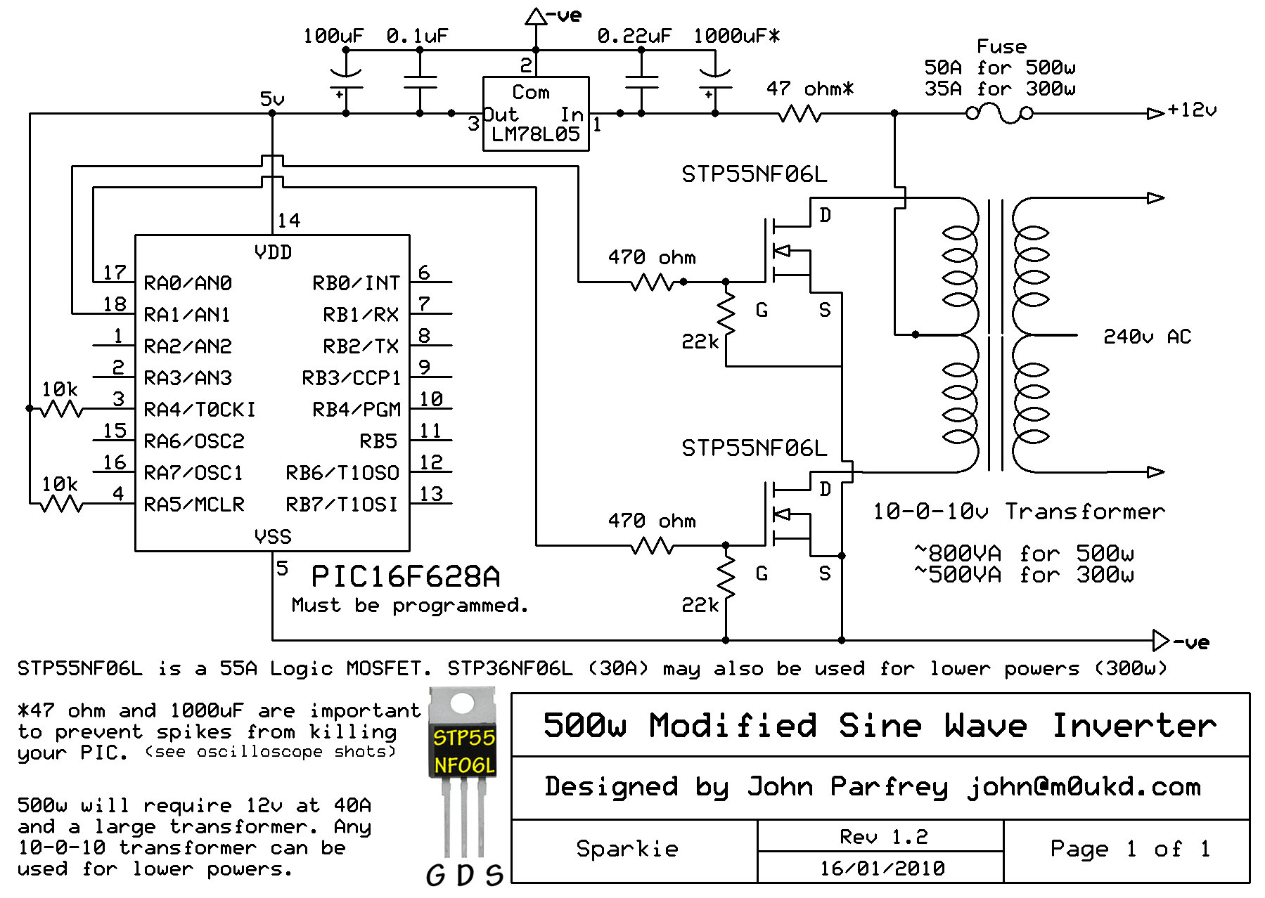
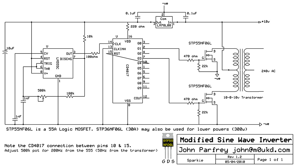
Here is a simple but powerful, stable and efficient schematic diagram for a 500w modified sine wave inverter circuit. Originally I used a 555 timer and a CD4017 decade counter to produce the modified sine wave, but then I thought a simple PIC micro controller with its internal clock would produce a stable 50Hz frequency without the need for two IC’s. As you can see its a very simple circuit. The CD4017 and 555 Timer circuit can be seen here should anyone want to try that.
Some information on this circuit. The PIC16F628A is programmed to produce a logic 5v signal for 5ms at pin 17 then 15ms off. Then the same at pin 18, 5ms on then 15ms off (4.17ms for 60Hz). That is one cycle which is then looped. This results in the signals below on the oscilloscope. (2 channel view) You can see the two 5v pulses from pins 17 & 18.
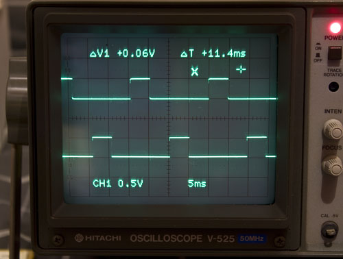
The two separate 5v pulses 180° apart
These two pins are then sent to the gates of the STP55NF06L (or STP36NF06L) logic MOSFET’s. These are special power MOSFET’s that require just 5v to switch on fully. They also have a very low 0.014Ω Source to Drain resistance when on which means they can switch high currents without wasting power as heat. This keeps the whole system efficient. They do run cool although a heat sink is required. The main losses in power will be within the transformer itself. They are capable of switching loads up to 55A (or 30A for the STP36NF06L) which makes this a powerful inverter if used with a large (~800VA) transformer. Of course you could use a smaller transformer for small loads. The MOSFET’s could be in parallel pairs for even more power. Just give each its own 470Ω gate resistor and a 22kΩ from each gate to source. I get around 240v AC from the 10-0-10 with a 12v battery but as this circuit is so efficient a 12-0-12 should give you no less than 220v AC at 12v. Of course if you live in a country with 120v, you can just use a 10-0-10v to 120v transformer. If you need 50Hz or 60Hz the PIC files ready to be programmed are at the bottom of this page. The transformer is wired up in reverse. We are using the low voltage side as the primary, and the high voltage side as the secondary. The low voltage side must be centre tapped. I might add I have not tried this circuit at 500w as I don’t have a large enough transformer at the moment, but the 55A MOSFET’s should be fine. I am going to rewind the secondary of a microwave oven transformer with about 11-0-11v and see how that goes, although I don’t think they are the most efficient transformer cores around. Still, it could be an easy and cheap way to make a 500w centre tapped transformer for this project. Will need some chunky primary wire! Its certainly not worth buying a large transformer for this project. For the price of that you could buy a commercial inverter or three. That’s no fun though is it! Also don’t forget that even to run a 100w load you will need 12v at almost 10A (calculator). Small sealed lead acid batteries are not going to be much help apart from to light your Christmas tree or charge your mobile phone.
The image below is the modified sine wave output you will get from this circuit. It is the same as most of the commercial inverters that are out there that aren’t pure sine wave. The advantage for the inverter with using a modified sine-wave is that the MOSFET’s are either fully on or fully off, never operating in their linear region which would cause heating and poor efficiency.
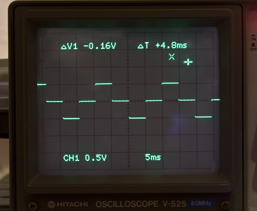
The modified ‘sine wave’, seen on the oscilloscope.
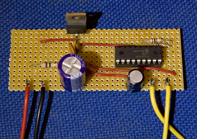
The prototype driver board.
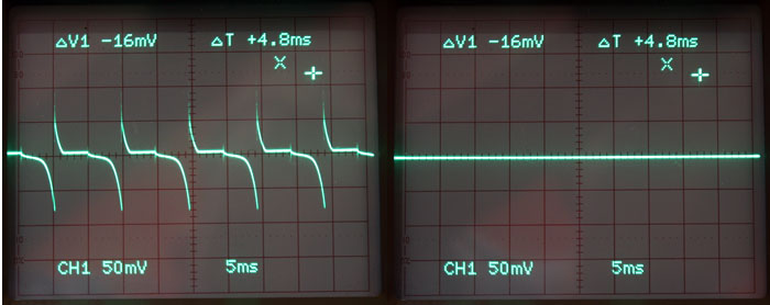
Note the large 1000µF capacitor and 47Ω resistor. These clean up the voltage spikes coming from the transformer centre tap into the positive rail and protect the PIC from them. I learnt the hard way and burnt out 2 PIC’s before looking into the problem with the scope. Don’t think that the 5v regulator will fix the spikes! It and the PIC got hot and then the PIC died. Twice! The image below shows what the power supply looks like at each end of the 47Ωresistor Left is power supply end and right is regulator end. This is with no load on the transformer. The spikes and waveform of them changes with load. The simple resistor and cap cleans it up. This works because the 1000µF capacitor will be seen as a low impedance to a voltage spike. The 47Ω resistor limits the current, so the spikes are dissipated in it as can be seen below.
If you wish to build this circuit you will need a PIC programmer to program the microchip with the HEX file below. I would be interested to hear from anyone who has built this circuit and what results you have had so please let me know!
| 50Hz HEX file for programming the PIC16F628A | 16F628A_50Hz_Inverter.zip |
| 60Hz HEX file for programming the PIC16F628A | 16F628A_60Hz_Inverter.zip |
Disclaimer: This circuit provides high voltage so great care should be taken not to become a part of the circuit when operating! Also this inverter produces a modified sine wave that is unregulated. If you put 15v in (or more) you will get much more than the 240v out just as with 10v you would get under 200v output. Output voltage differs with input voltage so as your battery discharges, so will your handy mains supply. While its fine running some light bulbs or simple mains equipment, I wouldn't use it for that new plasma TV or anything expensive if you are unsure! Most things will be happy with a modified sine wave and its certainly much better than the basic square wave inverters that are about. Bottom line is I accept no responsibility for damage to equipment or yourself as a result of the information on this page.
Hey friend i wanna try this. Just bought required material. Can you please tell me if you have the source file so, that i can add some other functions like i am gonna replace pic16f628 with pic16f877a to add an 16×2 lcd display.
And thanks for this detailed topic. I appreciate your efforts and thanks also for the hex files.
Hi.
Sorry, no longer have the source file, although it should be simple to create with many different microchips, even a picaxe!
Good luck, John.