
The MFJ-971 has the potential to be a great portable tuner. It is a small, compact tuner that has a sensitive SWR circuit allowing precise tuning with low power thanks to its 6w FSD setting and it has outputs for coax, wire and balanced feeder (although I won’t talk about the MFJ ‘heavy duty’ 1:4 voltage baluns here!). To make it the almost perfect portable / QRP tuner, there were a couple of things that needed to be solved…
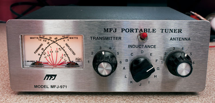
MFJ-971 Portable Tuner
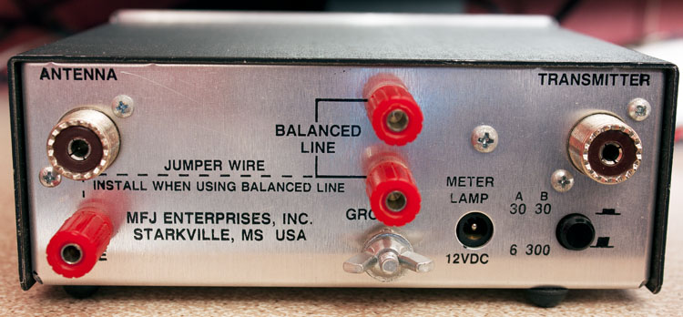
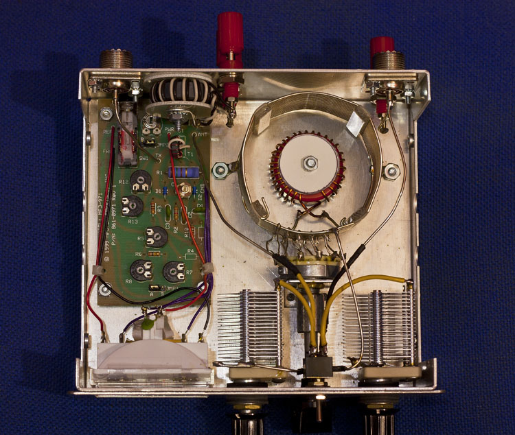
MFJ-971 rear
The problems I had with this tuner are:
- No bypass switch
- Not enough inductance to tune on 1.8MHz
The first thing that I would want in any tuner, is a bypass switch. Its nice to flick a switch and be able to receive on all bands and the lack of a bypass switch is frustrating. This was easily added by mounting a DPDT switch to the front panel, and connecting it appropriately, as seen in the pictures below.
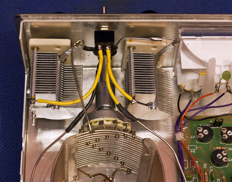
Bypass / Tune switch installed
Usually, the signal comes off the PCB and straight into the ‘transmitter’ capacitor and the output of the ‘antenna’ capacitor goes to the coax/wire connection on the rear. The switch has been added to provide a way to bypass the tuner section. A drawing of the DPDT switch wiring is below.
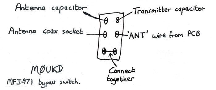
Switch connections
OK, now that annoyance is out of the way, lets fix the top band issue. MFJ say ‘The [MFJ-971] T-match tuner covers 1.8-30 MHz’. It may well do, if you want to match a perfect 50Ω load on 1.8MHz! The inductor inside this tuner, although adequate for 80-10m, does not have enough inductance to be useful on 160m.
To overcome this problem, I included extra inductance by winding 29 turns of enamelled copper wire (any suitable insulated wire will do) on a T130-2 iron powder toroid, so when the tuner is on the ‘L’ inductance setting, the whole original inductor is used plus the extra inductance provided by the toroid. This does not affect any of the other settings from A-K.
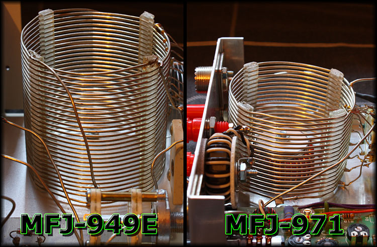
Inductor comparison
The MFJ-949E inductor has 27 turns, 75mm long and 75mm diameter which is about 37µH.
The MFJ-971 inductor has 17 turns, 43mm long and 66mm diameter which is about 17µH.
Adding on the extra inductance means we have a max inductance of around 27µH which allows matching on 1.8MHz.
Air inductance coils can be calculated here and the T130-2 toroid here.
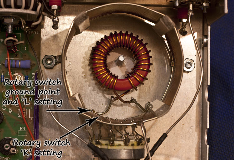
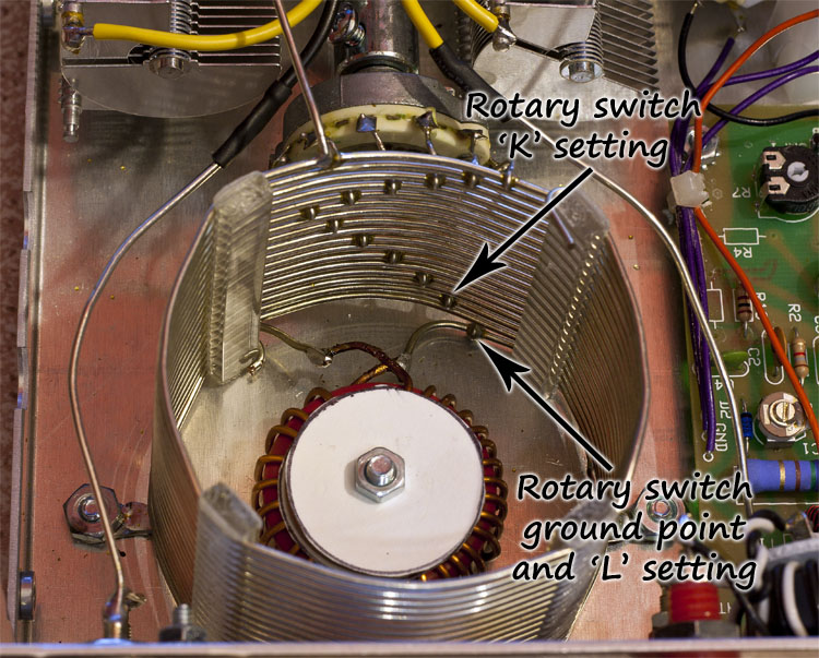
The inductor switch picks up its ground from the bottom of the inductor and this is also the ‘L’ setting, meaning the whole coil is in use when ‘L’ is selected. The ‘K’ inductance setting is 2 turns up from this point. I cut the wire just after the ‘L’ tap and inserted the extra inductance. Now, when ‘L’ is selected, the whole original inductor is in use, plus the extra inductance of the toroid, making it suitable for use on 160m! Of course, the ‘K’ setting still uses the whole original coil (less 2 turns) so nothing is really lost. The wires cross to keep any magnetic fields circulating the same way between the 2 inductors. The toroid is then fixed with a nut & bolt and suitable insulation washers either side of the toroid.
| The completed, modified, much improved MFJ-971 is seen below. Please let me know if you perform any of these modifications, I’d be interested to know what you think.There is one small problem remaining and that is RF BURNS! The nuts that hold the variable capacitors in place on many MFJ tuners are at RF potential. Most of the time they are hard to come into contact with being tucked away behind the control knobs, however, on the MFJ-971 the knobs must be pulled forward a little otherwise the metal inside the knob comes into contact with the metal shaft causing the grub screws that hold the two control knobs on to be at a high RF voltage. This can give you RF burns whilst you are tuning, even at 5 watts. I hate to imagine what the result would be if you put the ‘rated’ 200w into this thing and touched a control! One problem with pulling the knobs forward a little is that then the nuts themselves are more visible, although anything is better than an RF burn! 73 de M0UKD. |  |
The modified MFJ-971
Did you get RF burns with the MFJ 971 grounded?
The capacitors are insulated from the chassis, and the shaft of the capacitor is and must always be at RF potential. You cannot ground them, so yes.
John.
Hi John
How does the MFJ . 945 E, that is not described ?What the two variable capacitor ? pf -? pf
I would like to build a similar 945 E.
73 DX
HA0ZS
Hi Zsolt.
If you go to the MFJ website, you can download the manual which has the schematic for the MFJ-949E. It uses “208pf” variable capacitors. I would guess they are about 5-210pf. Not sure how they came about such a specific capacitance as 208!
Good luck! John.
Hi John
Any ideas where to get these two variable capacitors ?
73 DX
Hi Zsolt.
I don’t know, apart from buying them from MFJ.
Good luck, John.
I have used the slinky coils as inductor coils and work nicely,
Before I go ahead with these mods (especially the 160m). Is there any problems you have come across since doing them or is there anything you would do differently?
Hi Alastair.
I have not had any problems. I have thought of adding another switch marked L/M so that the original L setting could be kept, although I have not had a problem as it is. It might give some extra range on 80m. The extra L/M switch would just have to short the T130-2 inductor for ‘L’ and be open for the full, new ‘M’ setting.
Just a thought, I might add this one day. Not sure where I would put the switch yet!
Good luck and let me know how you get on!
Regards, John.
Thank you sir, did the toroid mod today and I can have a 1:1 match all the way down to 1.843 (don’t use the lower frequency modes). I bought a toroid from ebay, I know it’s cheating, but after I had a stroke last year, some things aren’t worth worrying about. It was about £4 delivered, had a lot less turns than yours, but thicker gauge wire. Stuck it on the little Chinese LCD component checker that I have, and it came in bang on 10uH.
Cutting the coil was the difficult part, it’s tougher than it looks, you don’t have a lot of room, and have to be careful not to damage things. I didn’t have a pair of long thin nosed snips. Eventually I got some fine nosed pliers and pulled the part of the coil to be cut, in towards the middle. That meant I could get a pair of tin snips (for cutting chicken mesh wire) on it and the job was done. Took seconds to solder it in and the job was done, quick test before screwing it back up The coil does a good job of holding the toroid in place, so I might just get a double sided sticky pad to keep it down – the ATU will only be used at home.
For me this was great, I have a G5RV. When I got it, I used 50ft of RG58 as always seems to be recommended – just lossy cable to hide the real VSWR. But the ATU worked on all bands. Then I put some quality RG213 on it and Top Band was not having any of it. I now have an ATU that covers everything again. Why MFJ don’t just add the toroid themselves, for the cost of a Dollar, I don’t know. But unlike some, I like MFJ stuff and this is the typical sort of easy thing to do with their equipment.
I have felt the RF through the screws from time to time (but as an M6, I’m unlikely to be running the sort of power that will really hurt) and I think I will do as some others have done and fill the screw hole with a plasticine type compound, that is the correct colour match.
The jury is still out on the bypass switch, I’m struggling to see the huge benefit, against drilling and fitting a switch in the front panel. Does it make that much difference? I can remember most of the ATU settings for each band like, T-2 I-F A-4, so it’s quite simple to tune straight on.
Hi Alastair.
Thanks for the update, it’s nice to know how it all went!
Well done John!
I also replaced the inductance rotary switch with a ceramic type.
The original MFJ tends to burns easy with RF voltage.
73 Fabio, IK0IXI
Hi John.
Can you tell me if it is possible to set the 971 as a straight through unit, using it simply as an SWR meter? If so, what are the capacitor and inductor settings?
Thank you,
Kevin GI6RBD
Hi Kevin.
Yes, you would have to open it up and disconnect the matching network and bypass it. There is no way by just adjusting the settings externally.
Cheers, John.
Thanks John.
Apologies for the slow acknowledgement.
Thank you John. I take it there are no settings which do this. I could add a by-pass switch as you have detailed.
Kevin
GI6RBD
No there isn’t. It’s permanently in tuned status. The bypass switch will allow use as a SWR meter.
Good luck! John.
Hi.
I was looking into the manual of the MFJ-945e and the 971. Seems like they are quite similar!
Is it possible to build in a 4:1 toroid balun into the 945e making it work with a balanced line?
How many turns is the toroide!?
All the best
Ted
Hi Ted.
Yes you certainly could. I would put in a 1:1 current balun, 10 bifilar turns on a ferrite toroid. You could use a switch on the back to place it in line.
73, John.
Thanks for the bypass info. Will 18 or 20ga. hookup wire be acceptable for the bypass mod? This unit will only be used at QRP power levels. Thanks!
hal
KB3HAA
Thanks! Yes for QRP, no problem.
Good luck! John.
Sir, Which MFJ tuner is best for a old 8 band tube radio from 1960? I wish to receive entire MW and all SW bands on the tube radio using the antenna tuner.
There are so many MFJ products which are confusing.
MFJ-16010
MFJ-956
MFJ-971
I wish I have a MFJ antenna tuner that will cover all bands and it should also have a T Match circuit. The current product MFJ-971 has a T Match but it does not seem to cover MW. The MFJ-16010 is a random wire tuner but it is not a T Match.
Any other antenna tuner other than MFJ?
Hi.
This is tricky. Most amateur radio antenna matchers will work from around 1800kHz up, so will be OK for SW reception. However, to cover MW (550-1700kHz) would require much higher inductance than that for SW.
Also, Amateur tuners, such as those from MFJ, are built for transmitting. Although they will work for receive, you do not need large capacitor spacing and big (in physical size) inductors. For receive on MW, a tapped ferrite inductor and close spaced (or polyvaricon) capacitors could be used, as there is no high voltage present.
Sorry I cant help with an ATU for MW, apart from building your own!
Good luck, John.
Could I get a schematic diagram showing the mods?
I am not quite sure of how the new coil is added to the “L” point. I think a little schematic would help a lot.
Thanks
73’s
9Z4GEM
I might add one at some point!
Thanks John. Nice.
Question: When in bypass mode, is not the inductance circuit still in line? (I want to use to manually prune/tune my antennas).
Thanks, Rick
Hi Rick.
No, when in bypass, the circuit is through VSWR meter only.
Cheers, John.