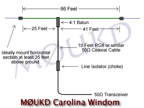
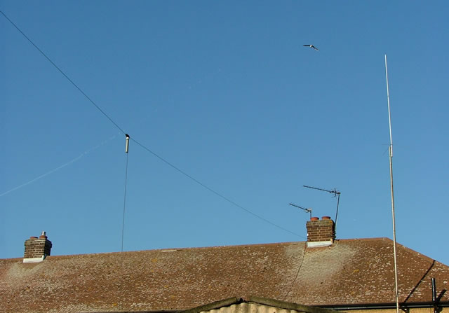
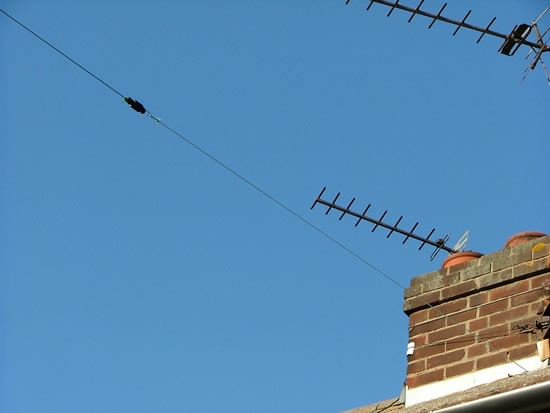
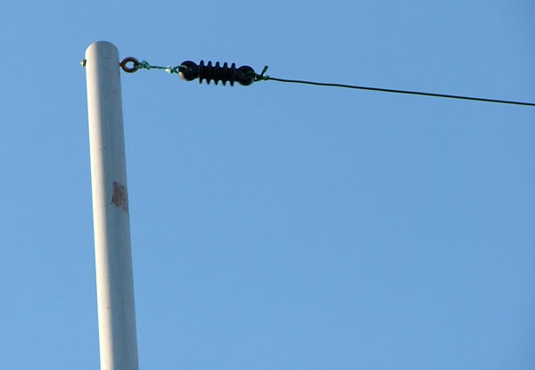
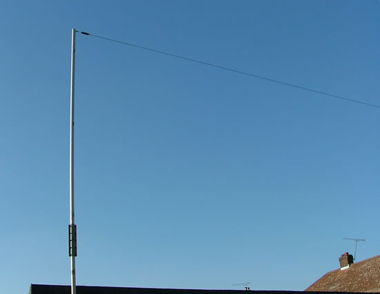
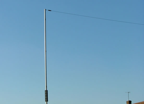
Here is my home HF antenna. It is an off centre fed dipole, with 10 feet of vertical radiator. It needs no tuner on 40m, 20m and 10m. It also works fine on all bands above 40m with a tuner, and even below 40m on 60m, and 80m, although the coax losses will be higher. I have even used it on 160m, but it is very inefficient there. Ideally, this antenna should be at least 35 feet above ground, but mine is currently about 25 feet, and still performs OK. The radiation pattern is improved if it is above 35 feet.
Holding true to the original Windom formulas, I used a ratio of 37.8% for one side and 62.2% for the longest side after determining the half wave length at the lowest operating frequency…. This is the 200Ω point, hence the 4:1 balun. (50Ω to 200Ω)
The 10 feet vertical radiator really does radiate, and offers vertical radiation to the existing horizontal radiation, and therefore adds to the low angle omnidirectonal radiation. The line isolator stops the vertical radiator radiating all the way back to the shack.
This is the same design as the ‘Carolina Windom 80 Special’ You can buy one of these for £109.95 but this cost nothing like that!
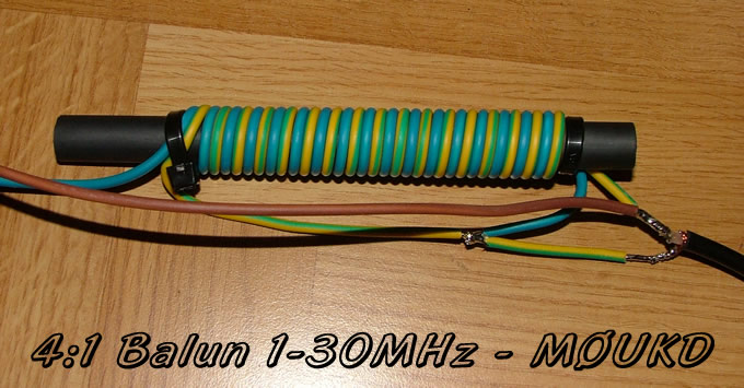
Here is the 4:1 balun. It is 17 bifilar turns on a half inch ferrite rod. 50Ω – 200Ω, 1-30MHz. Analyzer shows 1.1 SWR @ 50Ω to a 200Ω resistor from 1 through to 30MHz
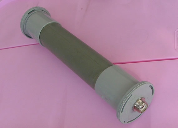
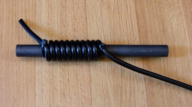
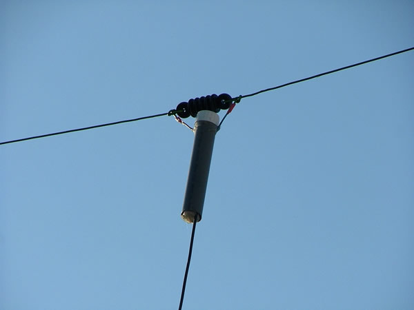
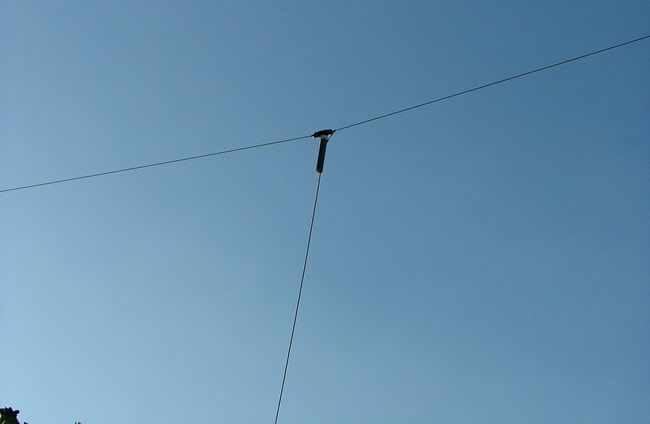
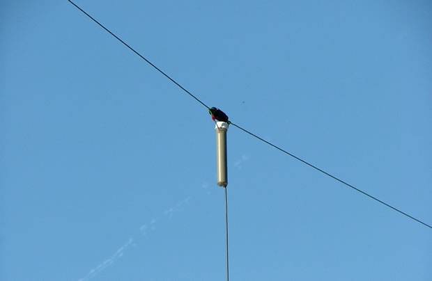
Line isolator. Made from PVC pipe with screw on end caps. You could just use a bare ferrite rod on the coax and save the connections.


Hello John.
Thanks for a most interesting and detailed description of how to make a Windom, Yep! , I may well give it a try. Thanks again.
Best wishes for the future
Paul
Dear John,
It is the cheapest and effective design of Carolina Windom found from internet resources. There are conflicting and confusing information all around. yours is straight forward and convincing. Scopes and limitations are very clear. Three of my friends are already using it. Now I will not search for those toroids and simply purchase the ferrite rods which costs only $0.3 (INR 20) in local market. Many thanks.
73s DE MANDAL
VU3MDL
dear mandal where u getting this ferrite rodes in india??
can u arrange few numbers for me??
search any old radio service shops.those days it was only s.w.and m.w. no fm like these days.fresh supply of ferrite rods and and coils are out of question.the same fate for old t.v.ribbon cable also.if u r makeing a g5rv you will have a tough time proucuring components. vu2ftf
Hi just getting back into HF. G5 FULL SIZE one side of garden. Making up a Windom for the other side of garden. Have 2 HF rigs. Have made a standard balun, should be OK for 50MHz & picked up a second hand radio works filter from the local W & S. Have loads of old Rod aerials so might give the a try. All best Bernie G0ENN. USED TO BE g6vzx.
Hi Bernie. Good luck with your antennas and i’m sure we will meet on the bands soon!
73, John.
Hi Bernie
thanks for sharing this project!
Just a mine stupid question: brown and blue wires..
Who is the 25” and 41” or it’s indifferent ?
73, Franco.
Hi Franco.
As its a balun, it shouldn’t matter. However, I would use the blue wire for the 25″ section as its the one that’s not directly connected to the centre of the coax. We want the coax to radiate at this point and to ‘make up’ for the off centre feed.
Good luck with your antenna! 73, John.
Thanks for the info. I built it and it works on 10,20, 18, and 40. It didn’t work on 15.
My first contact was North Carolina so I guess it is a North Carolina Windom 🙂 It seems to have solved all my problems.
Thanks again and 73’s
Dave KA3PMW
Hi John.
Many thanks for sharing this simple design.
I’ve had a bit of help from a friend in making a similar antenna, however, we made it to cover 80 thru 10. Our 4:1 transformer is of the “airwound” variety.
Installation is planned for later today, will let you know how it all goes.
Once again, Thanks for the info.
Rich de M6TGK
73’s
Hi. Nice plans for your Carolina windom. What gauge wire do you recommend for the 4:1 balun?
Thanks and 73
Randall VA1RJR
Hi Randall.
It’s not critical. I just used some wire from 3 core flex!
Good luck, 73, John.
Hi John…would things change much if I used ladder line instead of coax for the radiating element? Its from a 1/2 size G5RV thats not been as good as it could be and it also has a line RF block and PL259 already fitted.
2M0WFN
Hi Bill.
I dont think it would work as intended, as you would have another current somewhat cancelling the current you want to radiate in the vertical section. Why not just turn the G5RV into a doublet and run the balanced feeder all the way back to an ATU? I prefer a doublet as a multiband antenna as there are far less losses in the balanced feeder compared to coax when there is SWR on the line.
73, John.
Well….I sort of thought that may be the case, I was working of the idea that the section radiated and from that, it may do the job for me instead of a section of RG58.
The RG58’s not a problem, that will attach to the balun as normal, the coax then connection to the terminals on the RF Choke from the G5RV.
The G5 never has worked well hence the change, if results are broadly the same then I may have a local problem, 40m is dire while 20m and above is okay but not “jumping of the wall” great.
Local works due next year, after which I can look at getting my short beam in the air though?
-… -. -.-
I find that sliding the wire into a few inches of heavy silicone tube, before throwing a half hitch into the loop on the balun, both grips it nicely, prevents sharp kinks and bends, and does away with a fixture on top?
You do have to do your half hitch ‘manually’ so to speak? Thread on tubing, weave in and out to ‘build’ the hitch and solder other end inside balun. The silicon seals that nicely too.
This antenna is my first attempt at an HF setup after building several successful VHF antennas. I built this to specifications, with a prebuilt 4:1 balun, but even with the tuner I can’t get the SWR below 5:1 on 20m and it’s even worse on 40m. 12m and 10m tune quite easily. I’m about 25′-30′ up and in the clear. I’m calling it a night and will mess with it again tomorrow. Any ideas of where to start would be appreciated.
Hi Brian.
You could try switching the connections on the ‘balun’. It needs to be a voltage balun. Mine was never perfect anywhere, but enough to easily match with an ATU and not have huge losses in mismatched coax. I have not used this antenna for years, I replaced it with a simple doublet.
Good luck, John.
Just made a unun on ferrite rod, exactly same, but unun connected, excellant! Brian M6BAQ
I have made this antenna in summer 2015. It works quite good, but I was using an ATU with it. According to my antenna analyser RigExpert AA-30, it has no SWR lower than 2. What have I done wrong?
Hi Alex.
I’m not sure, the good thing is losses wont be too bad on the coax if its near enough.
Good luck! John.
Umm – How can the vertical 10ft section of co-ax radiate when there is a 4:1 balun at the feed point which is there to stop the co-ax from radiating?
It makes no sense. I don’t get it. Maybe I’m stupid or something but the whole vertical radiator thing sounds to me like an ambit claim in a union pay negotiation.
Whoops the cynic in me has been let out again – Bad Paul Bad, Bad, Bad …
Hi Paul.
Well, we are using a 4:1 ‘voltage’ balun and a voltage balun will not work as a choke, yet we are using an asymmetrical antenna, the shorter element wants to be longer and is coupled to the shield of the coax via the 4:1 voltage balun, causing it to radiate. This is then choked off by a choke further down the line.
Hope that makes sense!
73, John.
Try to pull down a longer side of wire (abouth 2-3 meters under ground level).
My antenna works fine!
73’ss de Mike
9a7bbw
Hello John,
I am planning for a new antenna, and the ‘Carolina Windom’ is one of my preferences.
You mention “It also works fine on all bands above 40m with a tuner”. Does that include the 12 m band (24.9 MHz)? I see no values in your SWR graph, that’s why I’m asking.
73s,
Roland, DL1EAL
Hi Roland.
I found it to work OK on 12m, although with a tuner. I have not used this antenna for many years now though, so cannot test for you.
Good luck, John.
I’m very interested in the construction details for the balun/unun. I understand the 17 bifilar turns, but how you’ve got them connected isn’t all that clear to me. Schematic?
Sorry, I should have done a schematic. If you look at the picture of the balun on the ferrite rod, you should be able to see the coax coming in from the right and the two wires coming out on the left side. The colour coding should also help.
Good luck! John.
How will this perform as a inverted V
It should work OK, although I have not tried it. SWR will be different. I would use a doublet myself!
Cheers, John.
Hi John,
An excellent description.
I plan to make a lightweight version for holiday use. I tend to do more operating then.
73
Nigel