
The finished End Fed Half Wave antenna coupler.
Centre fed half wave dipoles make great, simple and effective antennas for the HF bands. Sometimes however, the centre feed is not ideal, for example when you want to use it as a vertical. Being able to feed the dipole from one end gives you more options on how to erect an antenna and makes portable operation easier. A vertical, a sloper, a piece of wire hung in a hedge are all good examples. A ground mounted half wave vertical has a peak radiation angle of 20°, so it makes a good choice for DX.
I have been experimenting with feeding end fed half wave antennas matched by a parallel tuned circuit coupler. This article will explain my findings and reasons for constructing it the way I did.
A dipole can be fed anywhere along its length. A centre feed gives around 70Ω. A ‘Windom’ type off centre fed dipole (fed 38% along its length) provides around a 200Ω feed. The feed impedance at the very end of a half wave is thousands of ohms, usually somewhere between 2000Ω to 5000Ω, which we need to match to our 50Ω transceiver. The problem with end feeding a half wave is also its advantage. The high impedance means that the feedpoint has a very high voltage but low current, therefore very little ground is required. A very small counterpoise should be adequate from 7 to 30MHz, or you can even use the coax and transceiver as the counterpoise for an even simpler portable set-up. I included a switch to be able to use either. In practice, I have found Steve AA5TB‘s recommendation of at least 0.05 wavelengths to be accurate. Steve has done a lot of research with end fed half waves and I recommend having a read of his pages.
Below is the schematic of the final build.
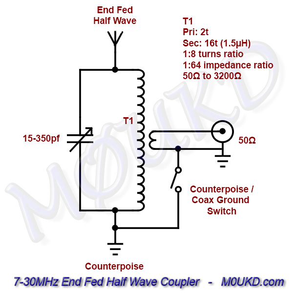
End Fed Half Wave Antenna Coupler Schematic – 7-30MHz
For calculating the length of a half wave in metres, I use 141÷ƒ(MHz) for wire elements. These dimensions were derived from modelling the antenna in EZNEC. I have found this calculation to work well, however it depends on many factors such as wire used, location etc. I have made a javascript calculator below for simplicity with a 15m half wave ready to go!
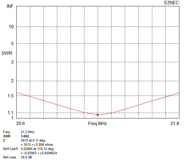
End Fed Half Wave (6.65m @ 21.2MHz, ground mounted) SWR – Actual bandwidth on the 50Ω side of the coupler will be much narrower, due to the tuned circuit we are using. This is showing the feed point SWR at 3200Ω
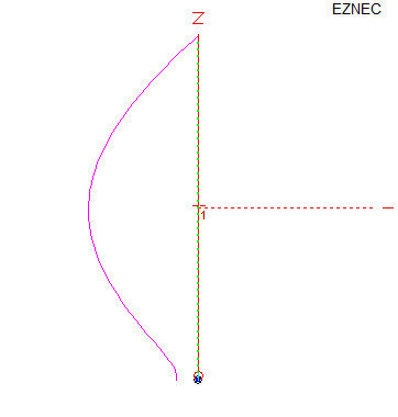
Current along the half wave. Notice how the feedpoint is not quite as high impedance as the top of the antenna.
First off, construction will be a juggle between available components and the desired band coverage. I had a capacitor that I wanted to use, which is a Johnson 154-2 air variable capacitor, with a range of 15-353pf. I would like to cover 7 to 30MHz with my coupler if possibe, so the next thing I needed to design was an inductor that would resonate in a parallel LC circuit at just above 30MHz when the capacitor is at minimum. Using this Resonant LC Calculator, I worked out that an inductance of 1.5μH will resonate at about 33MHz when the capacitor is at 15pf and 6.9MHz when the capacitor is at its maximum of 353pf. Sounds perfect to me! If you have a smaller value capacitor, for example 200pf maximum, it should still cover 10MHZ to 30MHz. A switch could be added to add a further capacitance of 150-200pf to include 7MHz operation.
So, lets build the secondary transformer inductor first. I wanted to transform 50Ω to around 3000Ω. This would require a 1:8 turns ratio. Impedance transformation is calculated by squaring the secondary turns ratio (note ratio, not actual turns) 8² is 64. 50×64=3200Ω (our input impedance x 8²). I looked at using a T200-6 iron powder toroid, but the problem was 1.5μH required only 12 turns. As I wanted a 1:8 turns ratio (for a 1:64 impedance ratio), I needed a primary of 1.33 turns, which was going to be impossible. I could have made it 16 turns and a 2 turn primary, but then the inductance would be too large for 30MHz.
So, I decided to use an air wound transformer. This way, I can build it with a 16 turn secondary, and at the inductance I wanted by altering the diameter and/or length of the coil. Using this Air Inductance Calculator, I worked out that a 19mm diameter, 52mm long, 16 turn inductor should give an inductance of 1.5uH, so this is what I built.
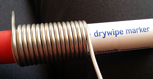
Winding the secondary inductor
Once it was wound, I tested it on an LC meter, which confirmed it was around 1.5µH. You can expand or contract the inductor to fine tune the impedance to suit. The importance is that it remains 16 turns to match with the 2 turn primary. I then wound the primary coil, which had to be a slightly larger diameter so that it could fit over the secondary coil and provide inductive coupling. You can see the finished 2 turn primary and 16 turn secondary below.
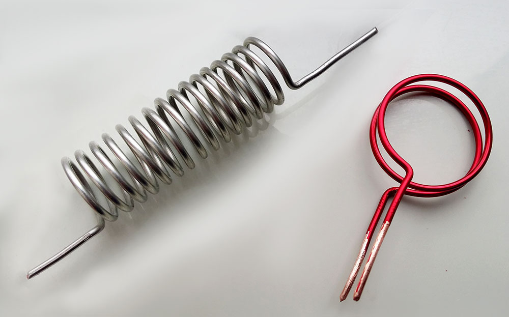
The completed inductors. They have their differences, but I will make them a happy ‘couple’!
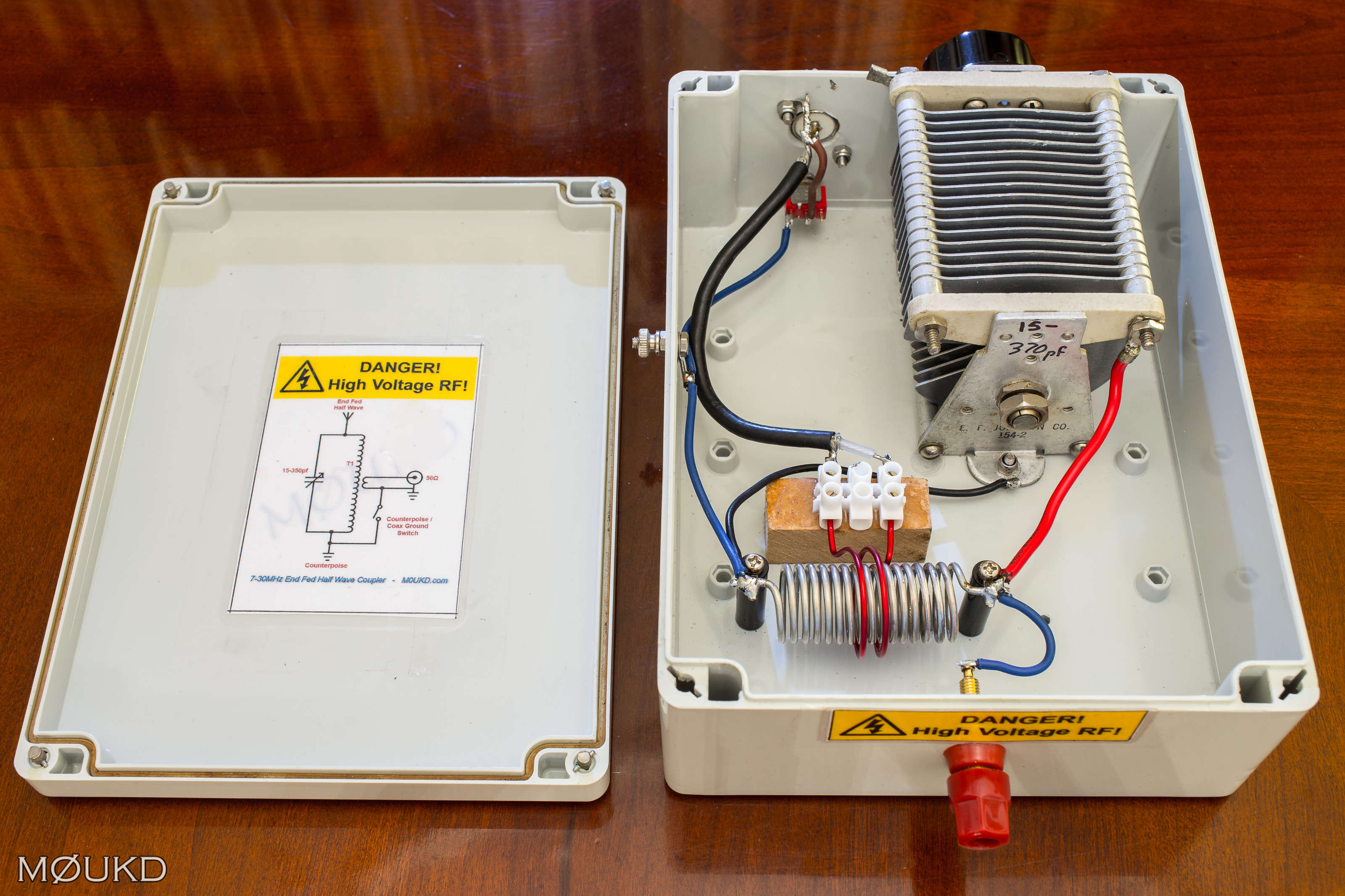
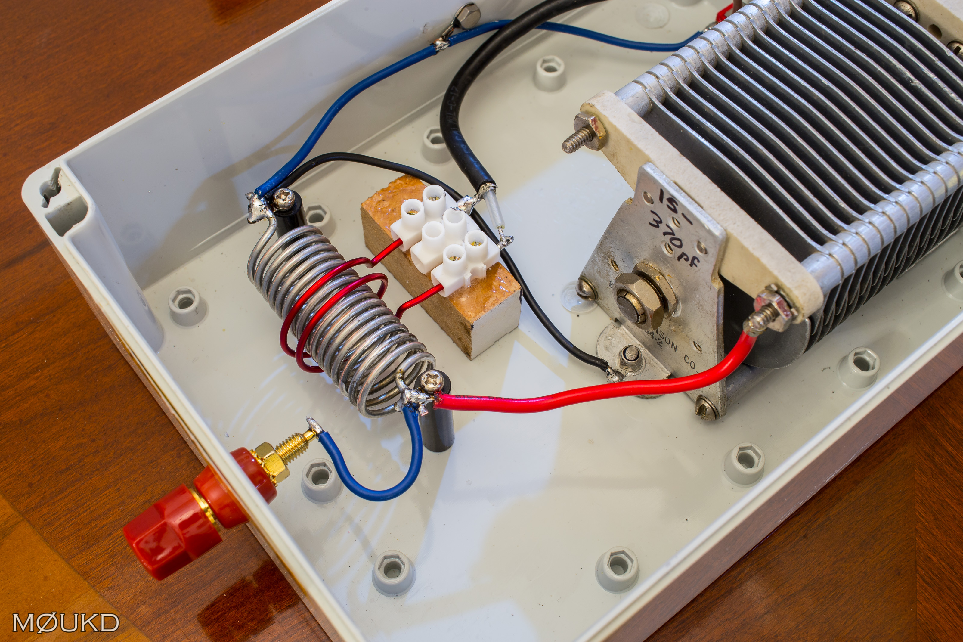
Now it was time to assemble it all into a box. The box I used came from a club ‘junk’ sale. It is a waterproof box that cleaned up well. It was a little fiddly mounting the inductors. I used some stand-offs for the secondary and a terminal block glued to a small block of MDF for the primary. The coax is soldered to the primary, the terminal block is just to hold it in place. There is a counterpoise connection on the side, the antenna connection on the front and the capacitor, SO239 and counterpoise/coax ground switch on the rear. Some photos of the completed unit are below.
The completed End Fed Half Wave Coupler
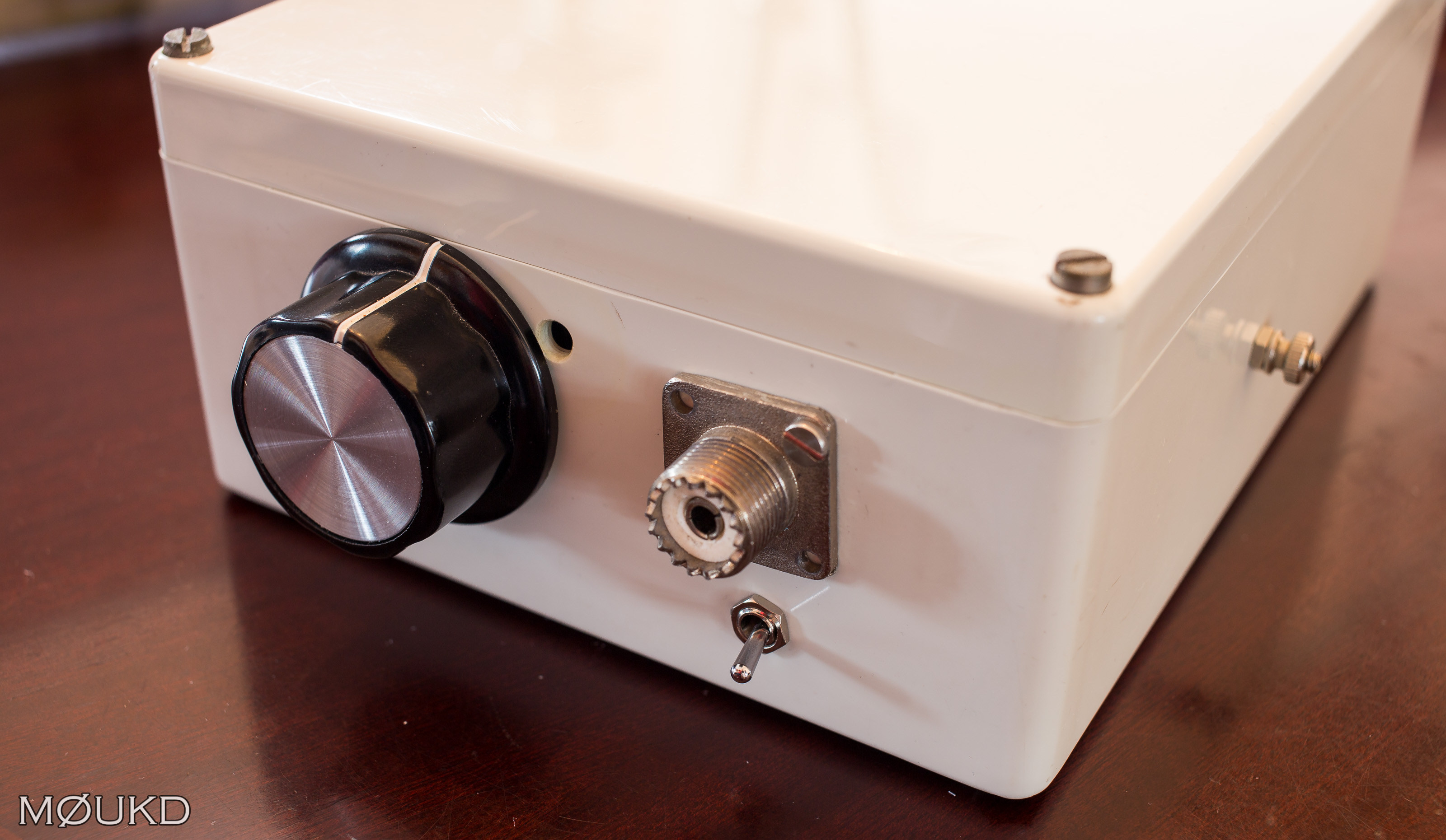
The tuning control, SO239, ground switch and on the right, the counterpoise connection.
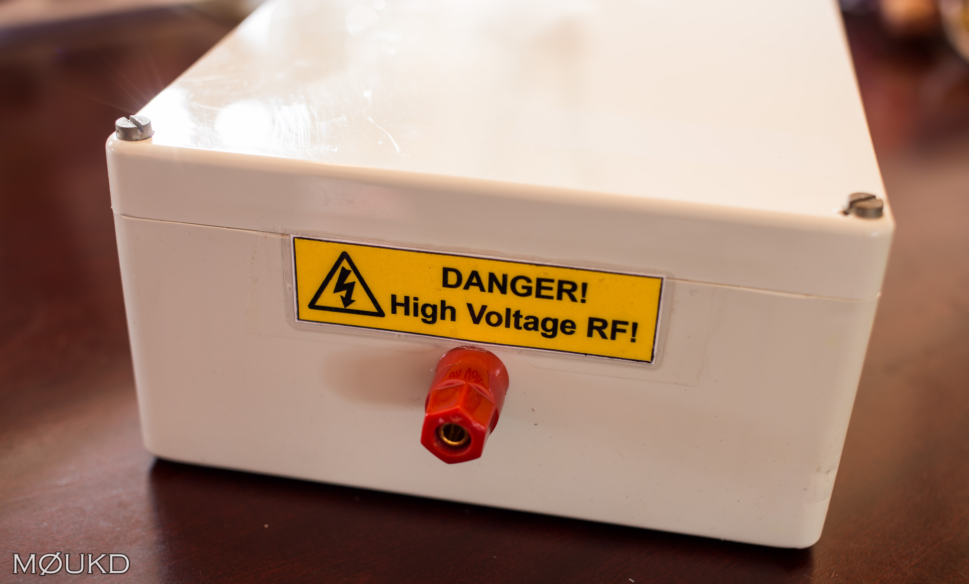
The antenna connection. The second hand box had a few holes in it, so I made this sticker to cover them up!
The unit worked exactly as designed. Attaching a 3.2kΩ resistor to the output, an input match of 1:1 SWR can be obtained from 6.5MHz to 30MHz. The frequency was a little bit lower than I calculated, but I guess this is due to extra stray capacitance. I tuned the coupler to resonance into a resistor (in my case 3.2kΩ) so a 1:1 SWR was obtained on my chosen frequency of 21.25MHz, then I removed the resistor and attached the half wave antenna (6.65m) and counterpoise (66cm) from the above calculator. Without adjusting the variable capacitor, I had a 1:1 SWR. This confirmed that I had a resonant half wave and that I was feeding it at or very close to the peak voltage point and the feed impedance was around 3200Ω. I found that a small counterpoise was required. Sometimes, the stray capacitance to ground was good enough on its own, especially on the higher bands and if the coupler was laying on the ground. If its all away from ground, I get consistent results using the above setup. I have had good success also by using the coax as the return, by connecting the ‘bottom’ of the primary and secondary together via a switch to use the coax shield and transceiver as a counterpoise.
You may be able to adjust the capacitor to match the antenna if its not a perfect half wave, but then it will be a higher current feed and the simple ground system will be inadequate. The coupler will also not be working as it was designed and will be inefficient, generating heat. The coupler is a tuned impedance transformer, not an antenna ‘tuning’ unit. Stick to the above, and it should be a sure thing!
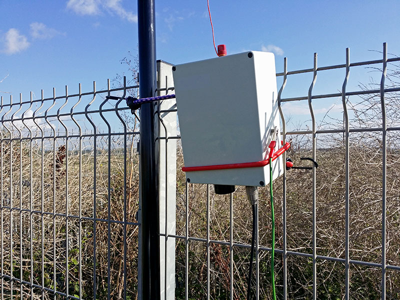
Feeding a 21MHz half wave
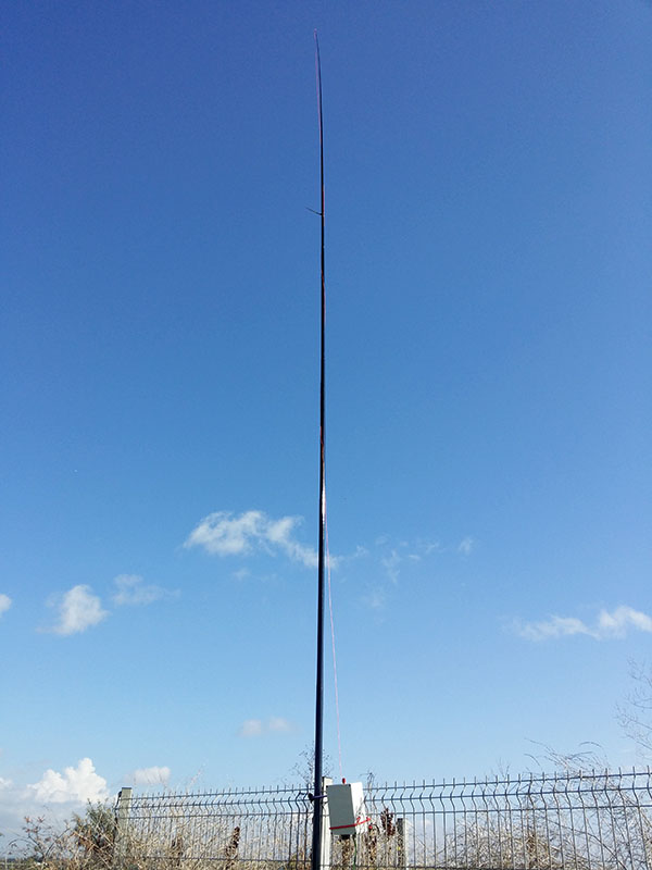
A half wave vertical for 21MHz. 6.65 metres of wire on a 9 metre fibreglass pole. The coupler is mounted 2 metres up and attached to the top of the fence. The 67cm counterpoise just hangs down in free air.
Below is a short video from my second test with the coupler, here on 17m.
Hi John,
If I’d like to add 60M to this design, would it work by adding a 300pf doorknob to it?
Thank you in advance for your reply.
Kind regards, Olaf
Hi Olaf.
That should be fine. Give it a try!
73, John
Hallo John
Nice description of building. I have a question: What is average bandwith withouth retuning.
Thank you for your answer.
73 Janez
Hi Janez.
It’s quite low due to the high Q of the tuned circuit. Next time I use it I will take some measurements and add them to the page.
73, John.
So simple and logical way to explain how to reach the target ! Congratulations and thank you for this nice antenna lesson
So simple and logical way to explain how to reach a target! Congratulations and thank you for the nice antenna lesson.
I like the concept of link coupled tuners.
I would like to build one for a 180 foot long wire for 160 meters.
Large copper coils….. maybe mount in a plastic garbage can or plastic barrel.
W4DNR
Thanks for the information and links provided.
I have been wondering of ground systems in HF-manpacks with whip antenna. There are always suggestions to use them with ground stakes, counterpoise wires etc. if possible, so I suppose they are usual coil loaded quarter wave vertical whips.
Have you ever try/heard of shortened (loaded whip) end fed half wave antenna? It sounds like quite obvious solution for manpack whip on HF. Or am I missing something?
I haven’t seen any, although there’s no reason why not. You would have to experiment though, it would be another thing to get right!
Perhaps I’ll try it some time, say on 80m.
Good luck, John.
Very nicely done!
Do you have to re-tune the capacitor for each band?
Do you foresee any problems using this on a sailboat for a vertical or sloper wire antenna?
Hi Richard.
Yes, the capacitor and inductor create a resonant circuit, which must be tuned to the operating frequency for efficient power transfer between primary and secondary.
Cant see why it wouldn’t work on your sailboat, sounds nice!
Good luck, John.
Where did you get the variable capacitor from?
I want one for an end feed antenna.
I have a 10meter squid pole ready for the end feed antenna.
73’s
Barry Salt
VK4BAS/ZL2TSP
Hi Barry.
This come from eBay, they come up occasionally.
Good luck with your antenna!
John.
Good day John, this is a thing of beauty! Thank you for the nice article.
This specific type of matching is known as a “Fuchskreis” and was invented by an Austrian fellow called Joseph Fuchs OE1JF in 1927. In those days it was even simpler to match as all transmitting equipment was tube driven and this already had a very high output impedance.
Interesting to hear that everybody ends up with this 2300 Ohm to 3500 Ohm feedpoint impedance. I use EFHWs that are driven by a low pass as impedance match, much like the original Par Endfedz and had the same experience.
Will build one of yours, I am very motivated now.
Thank you for sharing this project John.
73 & best of DX to you om
Hi John.
Thanks for presentation. I finished my coupler few days ago. It works great!
73 Tuomas
Nothing FANCY but easy to build and practical!!! However I have a question, what did you use to measure/verify the inductor’s 1.5uH? Do you recall the meter’s test frequency if used? I suppose one could ball-park this by building a parallel resonant tank and a O-scope ensuring the 1.5 uH with a 1% rf cap in parallel assuring correct resonance, and of course a series 50ohm termination might be good enough?
Hi Duane.
I used my Almost All Digital Electronics L/C Meter IIB. Yes you could measure the resonant frequency with a fixed capacitor in parallel and work it out that way if you don’t have access to an LC meter.
Good luck! John.
I find that an end-fed half-wave is a great holiday antenna. The tuner (for low power) can be made quite small, and 10 metres of wire provides 20m and 10m bands, and with a bit of tweaking 6m as well. The wire can be wrapped up small and the whole thing fit into quite a small space.
What gauge wire did you use for the secondary? I tried #18 enamel but not stiff enough. I have some #14(common house wire) and give that a try. Thanks for a great portable antenna idea.
Ken VA3ABN
Hi Ken.
I can’t remember what gauge I used, but I just used something thick enough to self support sufficiently.
Good luck with it! 73, John.
Hi John,
Adding a 300pF doorknob capacitor adds 60M and works just fine.
For a quick band switching I used banana male and female connector cables.
So first part is 10M, next part will tune 12M and so on…
Best 73s de Olaf PE1PMD
Hi John,
Is there a way to calculate the capacitor voltage rating in order to use more than 100Watts?
SV2HJZ 73s
Hi Vasilis.
Yes there is. If you take your power, lets use 500W as an example, and the impedance, in this case 3200Ω, the voltage across the capacitor will be 1265 Volts.
The calculation for this is the square root of the watts*impedance. Or, just use the calculator below!
Good luck!
http://m0ukd.com/calculators/ohms-law-calculator/
Great information. Thanks for posting/
Hi John
Thanks for dharing this project.
What is the max operating power?
73 Med cn8yr
I’m not sure really. Only used it with 100W and it’s been fine.
Should be OK as long as it’s tuned correctly and the impedance is correct I would have thought.
73!