
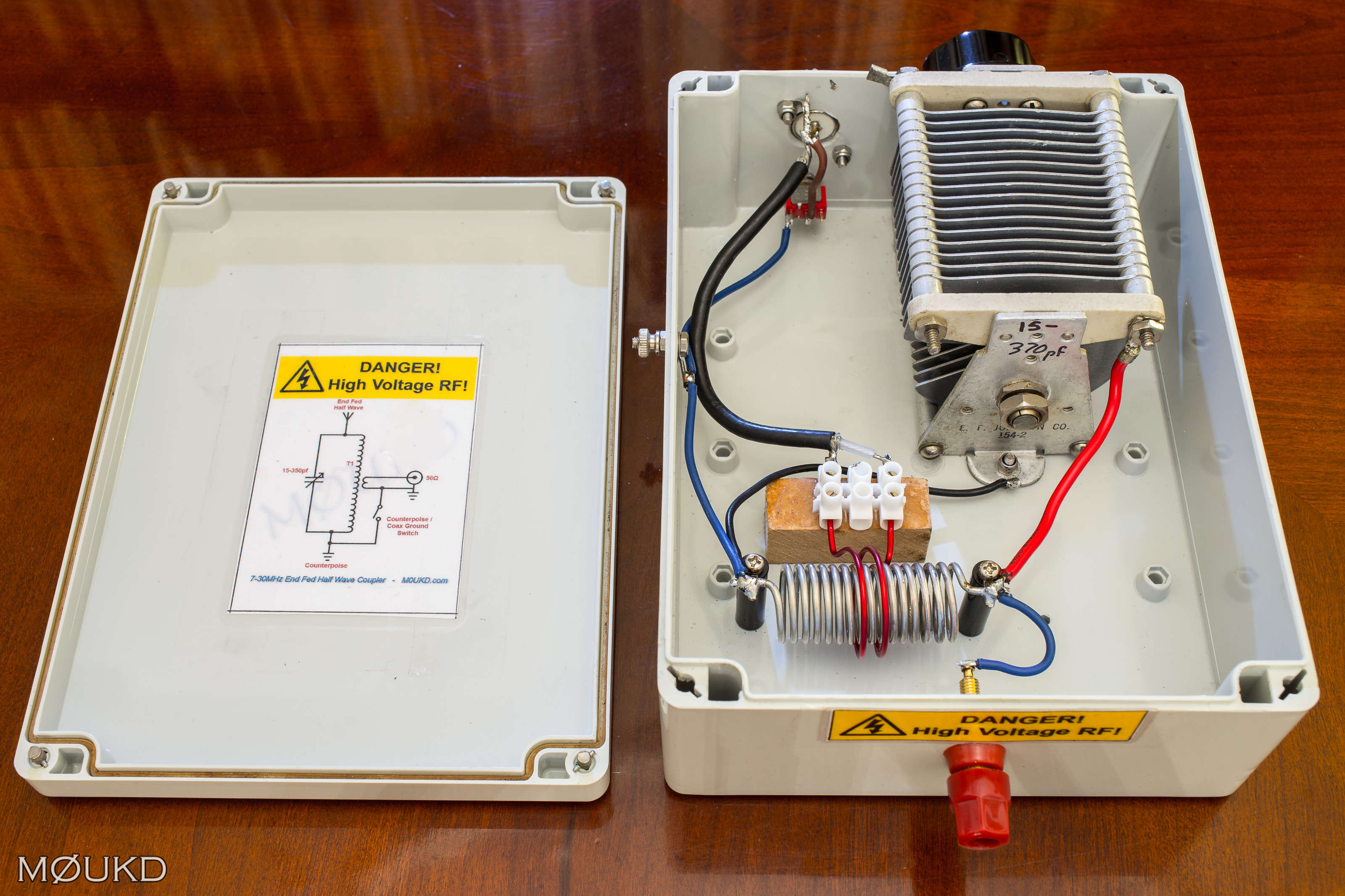
The finished End Fed Half Wave antenna coupler.
Centre fed half wave dipoles make great, simple and effective antennas for the HF bands. Sometimes however, the centre feed is not ideal, for example when you want to use it as a vertical. Being able to feed the dipole from one end gives you more options on how to erect an antenna and makes portable operation easier. A vertical, a sloper, a piece of wire hung in a hedge are all good examples. A ground mounted half wave vertical has a peak radiation angle of 20°, so it makes a good choice for DX.
I have been experimenting with feeding end fed half wave antennas matched by a parallel tuned circuit coupler. This article will explain my findings and reasons for constructing it the way I did.
A dipole can be fed anywhere along its length. A centre feed gives around 70Ω. A ‘Windom’ type off centre fed dipole (fed 38% along its length) provides around a 200Ω feed. The feed impedance at the very end of a half wave is thousands of ohms, usually somewhere between 2000Ω to 5000Ω, which we need to match to our 50Ω transceiver. The problem with end feeding a half wave is also its advantage. The high impedance means that the feedpoint has a very high voltage but low current, therefore very little ground is required. A very small counterpoise should be adequate from 7 to 30MHz, or you can even use the coax and transceiver as the counterpoise for an even simpler portable set-up. I included a switch to be able to use either. In practice, I have found Steve AA5TB‘s recommendation of at least 0.05 wavelengths to be accurate. Steve has done a lot of research with end fed half waves and I recommend having a read of his pages.
Below is the schematic of the final build.
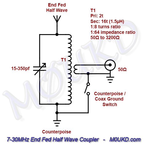
End Fed Half Wave Antenna Coupler Schematic – 7-30MHz
For calculating the length of a half wave in metres, I use 141÷ƒ(MHz) for wire elements. These dimensions were derived from modelling the antenna in EZNEC. I have found this calculation to work well, however it depends on many factors such as wire used, location etc. I have made a javascript calculator below for simplicity with a 15m half wave ready to go!
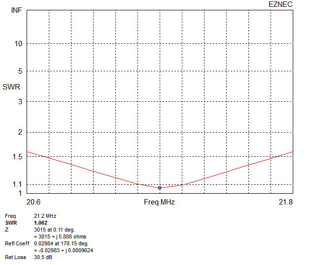
End Fed Half Wave (6.65m @ 21.2MHz, ground mounted) SWR – Actual bandwidth on the 50Ω side of the coupler will be much narrower, due to the tuned circuit we are using. This is showing the feed point SWR at 3200Ω
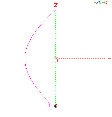
Current along the half wave. Notice how the feedpoint is not quite as high impedance as the top of the antenna.
First off, construction will be a juggle between available components and the desired band coverage. I had a capacitor that I wanted to use, which is a Johnson 154-2 air variable capacitor, with a range of 15-353pf. I would like to cover 7 to 30MHz with my coupler if possibe, so the next thing I needed to design was an inductor that would resonate in a parallel LC circuit at just above 30MHz when the capacitor is at minimum. Using this Resonant LC Calculator, I worked out that an inductance of 1.5μH will resonate at about 33MHz when the capacitor is at 15pf and 6.9MHz when the capacitor is at its maximum of 353pf. Sounds perfect to me! If you have a smaller value capacitor, for example 200pf maximum, it should still cover 10MHZ to 30MHz. A switch could be added to add a further capacitance of 150-200pf to include 7MHz operation.
So, lets build the secondary transformer inductor first. I wanted to transform 50Ω to around 3000Ω. This would require a 1:8 turns ratio. Impedance transformation is calculated by squaring the secondary turns ratio (note ratio, not actual turns) 8² is 64. 50×64=3200Ω (our input impedance x 8²). I looked at using a T200-6 iron powder toroid, but the problem was 1.5μH required only 12 turns. As I wanted a 1:8 turns ratio (for a 1:64 impedance ratio), I needed a primary of 1.33 turns, which was going to be impossible. I could have made it 16 turns and a 2 turn primary, but then the inductance would be too large for 30MHz.
So, I decided to use an air wound transformer. This way, I can build it with a 16 turn secondary, and at the inductance I wanted by altering the diameter and/or length of the coil. Using this Air Inductance Calculator, I worked out that a 19mm diameter, 52mm long, 16 turn inductor should give an inductance of 1.5uH, so this is what I built.
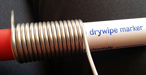
Winding the secondary inductor
Once it was wound, I tested it on an LC meter, which confirmed it was around 1.5µH. You can expand or contract the inductor to fine tune the impedance to suit. The importance is that it remains 16 turns to match with the 2 turn primary. I then wound the primary coil, which had to be a slightly larger diameter so that it could fit over the secondary coil and provide inductive coupling. You can see the finished 2 turn primary and 16 turn secondary below.
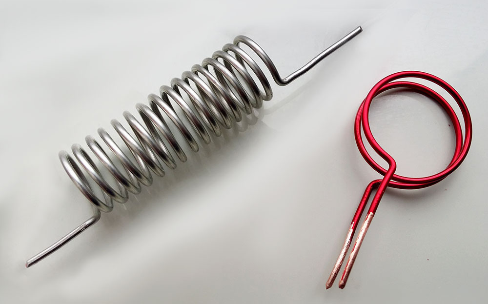
The completed inductors. They have their differences, but I will make them a happy ‘couple’!
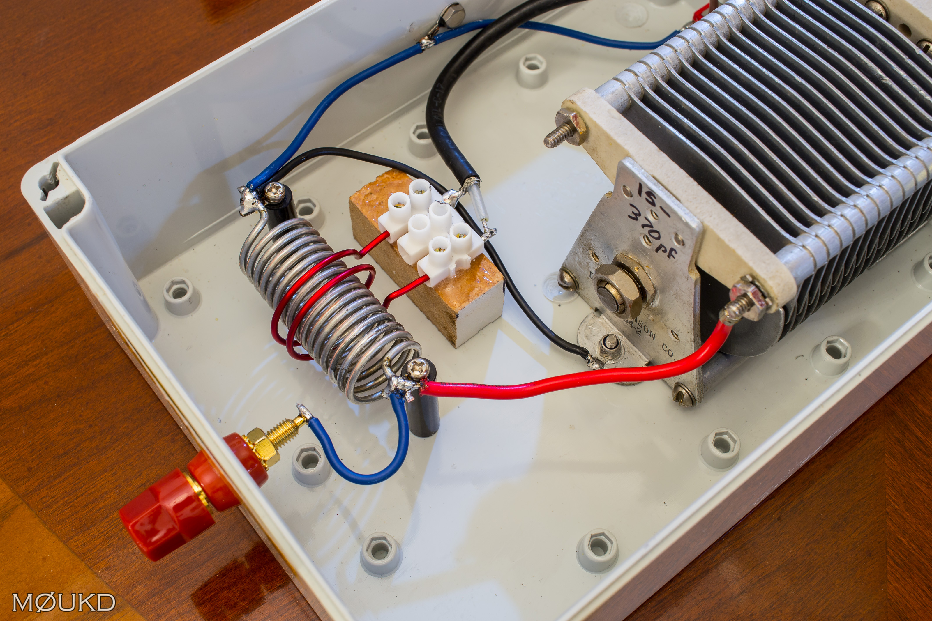
Now it was time to assemble it all into a box. The box I used came from a club ‘junk’ sale. It is a waterproof box that cleaned up well. It was a little fiddly mounting the inductors. I used some stand-offs for the secondary and a terminal block glued to a small block of MDF for the primary. The coax is soldered to the primary, the terminal block is just to hold it in place. There is a counterpoise connection on the side, the antenna connection on the front and the capacitor, SO239 and counterpoise/coax ground switch on the rear. Some photos of the completed unit are below.
The completed End Fed Half Wave Coupler
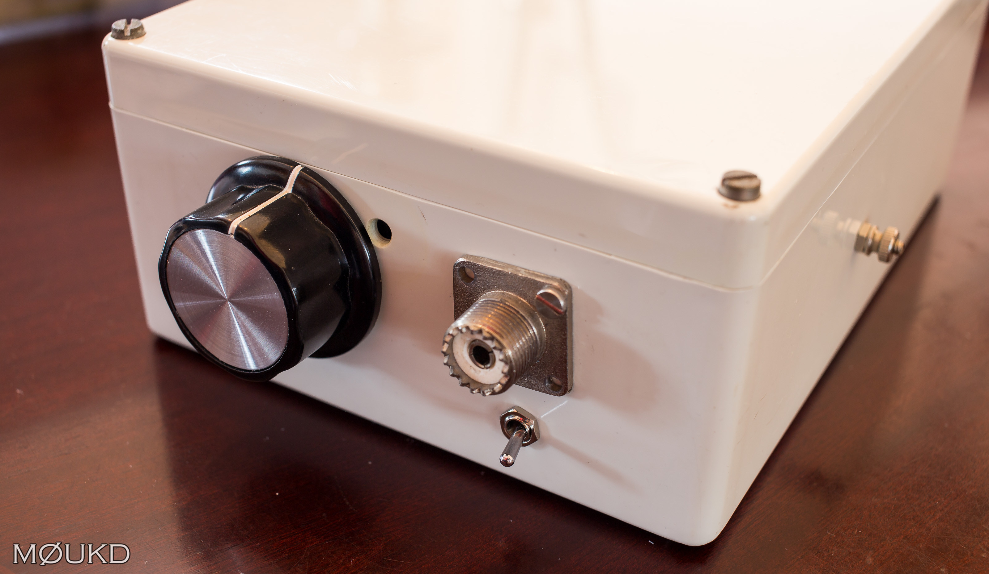
The tuning control, SO239, ground switch and on the right, the counterpoise connection.
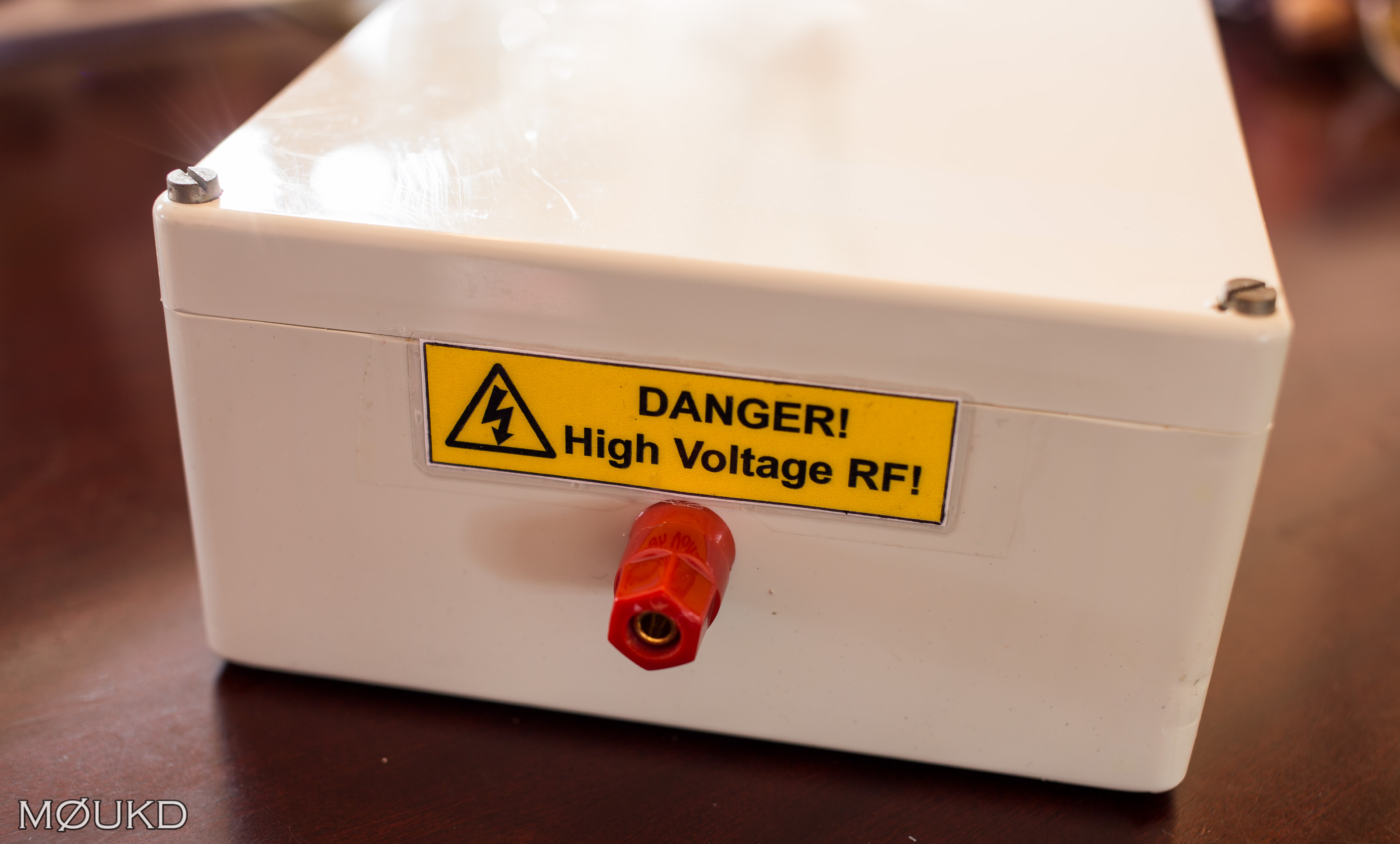
The antenna connection. The second hand box had a few holes in it, so I made this sticker to cover them up!
The unit worked exactly as designed. Attaching a 3.2kΩ resistor to the output, an input match of 1:1 SWR can be obtained from 6.5MHz to 30MHz. The frequency was a little bit lower than I calculated, but I guess this is due to extra stray capacitance. I tuned the coupler to resonance into a resistor (in my case 3.2kΩ) so a 1:1 SWR was obtained on my chosen frequency of 21.25MHz, then I removed the resistor and attached the half wave antenna (6.65m) and counterpoise (66cm) from the above calculator. Without adjusting the variable capacitor, I had a 1:1 SWR. This confirmed that I had a resonant half wave and that I was feeding it at or very close to the peak voltage point and the feed impedance was around 3200Ω. I found that a small counterpoise was required. Sometimes, the stray capacitance to ground was good enough on its own, especially on the higher bands and if the coupler was laying on the ground. If its all away from ground, I get consistent results using the above setup. I have had good success also by using the coax as the return, by connecting the ‘bottom’ of the primary and secondary together via a switch to use the coax shield and transceiver as a counterpoise.
You may be able to adjust the capacitor to match the antenna if its not a perfect half wave, but then it will be a higher current feed and the simple ground system will be inadequate. The coupler will also not be working as it was designed and will be inefficient, generating heat. The coupler is a tuned impedance transformer, not an antenna ‘tuning’ unit. Stick to the above, and it should be a sure thing!
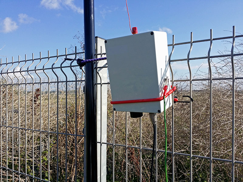
Feeding a 21MHz half wave
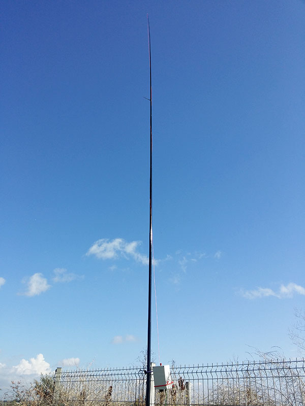
A half wave vertical for 21MHz. 6.65 metres of wire on a 9 metre fibreglass pole. The coupler is mounted 2 metres up and attached to the top of the fence. The 67cm counterpoise just hangs down in free air.
Below is a short video from my second test with the coupler, here on 17m.
Very nice presentation. Great looking setup. Congratulations. de w4qo
Thanks Jim! Enjoying using it so far 😉
i would try this tuner with other specifications on 160m. do you have those????
’73
Hi.
Yes, you could certainly build it for 160m. It would require a toroid and a larger capacitance. A half wavelength for 160m is of course 80m long though!
73, John.
Hi John, to make sure I am understanding the calculations correctly, what was the inductance of the primary coil?
Excellent job by the way.
-Morgan
Hi Morgan.
I never measured or calculated the inductance of the primary coil. The secondary coil is whats important to get the resonance where you want. The primary coil will inductively couple to the secondary efficiently when the secondary is resonant at the same frequency as we are feeding into the primary coil. All we need to worry about is the turns ratio between the two coils and the secondary inductance for resonance with the selected capacitor.
Hope that helps. Good luck if you try it!
73, John.
Nice report OM. Looking at the “Feeding a 21MHz half wave” picture, I wondered if the METAL fence could cause some problems with the antenna coupler housed in the plastic case. Do you think it was a factor here?
Hi Don.
I don’t think it was a problem. It seemed to work well. I have used the coupler with a stray capacitance to earth as a ‘counterpoise’ before 😉
73, John.
Thanks for the info John. I think I’ll be putting one together here for our field day in the States. Thanks for the great writeup!
-73, Morgan, NS0R
Thanks Morgan, good luck with your build!
John.
Fantastic writeup! Thank you for documenting your work so well. Looks like a great companion to the 897 for portable operation.
Thanks Joe!
I sure do like using it 🙂
Regards, John.
¡Nice article, congratulations!
The “Stray capacitance” you mentioned, is the 12 pf per meter (Tube) or 8 pf per meter (Wire).
You must add this value, to calculate the resonance.
OTOH, you can connect the coaxial to a derivation in the cold end of the coil. Look the best coupling; just as you do with the 2K4 resistor, or the tube as is.
A 1″ tube will need about 2K2 and a wire 4K7 in standard values.
Edgardo Maffia – LU1AR
Buenos Aires – Argentina
John,
Is it an illusion, or do you have 16 turns on the secondary coil in the finished picture, versus the 14 in the unassembled picture of the primary/secondary coil?
Hi Morgan.
No, you are correct. The photos of the unit are from when I had 16 turns, but after some testing, I found 14 turns to be a better ratio. I just haven’t got around to updating the photos! I will do soon.
Well spotted. 73, John.
Hi again John,
I have a question, and sorry for my ignorance. Steve says on his page:
“First, setup your end fed half wave tuner (ex., parallel tuned circuit link coupled) with a resistor across the output as shown on the schematic below. The resistor should be the value that is appropriate for the turns ratio of the coupler. For example, use something close to these values:
10:1, 5000 ohms (4.7k 5% standard value)
9:1, 4050 ohms (3.9k 5% standard value)
8:1, 3200 ohms (3.3k 5% standard value)
7:1, 2450 ohms (2.2k or 2.7k 5% standard value)
6:1, 1800 ohms (1.8k 5% standard value)”
So, you re adapting for a 2450 ohms impedance. But aren’t cable ends much higher than that? Like 5k ohms? Why didn’t you use 10:1 ratio?
Thanks and sorry for bothering!
Francisco
Hi Francisco.
In tests, I found a 7:1 ratio to be good. I did start with a 10:1 but 5k was too high impedance. Then I went to 8:1 which was OK and finally settled on 7:1. I think in reality, the impedance is not as high as 5k. If I built another, I would probably use 8:1 as its a happy medium!
Good luck, John.
Hi John
I built the coupler and it works! I modeled it out and I also came to the conclusion that a 7:1 impedance was the best. That being said, I have not been able to get as low of an SWR as I would have imagined with the 7:1 ratio. The best I’ve been able to do was about 1.6 on 15 and 20 meters using the appropriate lengths of wire. I have plenty of capacitance to spare, I just think that I too should have used an 8:1 ratio. For the time being, 1.6 will work. Then we will have approximately 100 feet of coax from our transmitter to the antenna at our field day site, and the loss should lower the SWR. Perhaps I’ll try the 8:1 ratio. I still have plenty of time to rebuild the box before field day. Thanks again for the excellent writeup.
-Morgan
Hi Morgan. Nice to hear about your tests with the coupler. Yes it can be a bit fiddly to get the SWR close to perfect. There are so many variables. The lower impedance of the 7:1 gives you a little leeway. As you go up it all gets a bit more critical. I have rebuilt mine with a 8:1 ratio for now. You could try playing with the length of the counterpoise. The main thing is to tune the LC circuit to resonance (into your 2.4k resistor for example), then adjust the length of wire or counterpoise to give the lowest SWR.
Good luck for field day! 73, John.
Seems to me that, if the antenna and feed can have a common ground, then the coupling coil could be dispensed with and the feed line connected to a tap a turn or two up on the resonant coil. This should make it possible to adjust for an exact match. Not so easy in the field, unless a sliding clamp can be made, but surely possible. Anybody tried this?
Well, we used this set up for Field Day. It was pulling my son’s hair out and I said it does not have enough coupling. I told him just bring the box over to me and lets take a look. We pulled off the 2 turn primary coil and wound a 3 turn coil and bingo it worked great. But, we were using a t140-4 or 6 toroid. It worked like a champ. For 40 meters i pulled out an old roller inductor connected a 200pf cap across it parallel and then connected the coax center to the roller tap and shield to be bottom and counter poise connection and we had 2 knobs to play with. Fastest match i have ever had. We worked a bunch of 40. We were 4A in Kansas and worked over 2100 contacts half on cw which is what we were using. Our other antennas were off center fed dipole for 80-40-20-15, half square on 40 and of course the 20 meter EFHW vertical. We tuned the half square at the base using this same box. Worked great. 73. Great article. NJ8M Dad, NS0R Son…the original Morgan above.
Hi John.
Thanks for nice article,very precise to understand.
I also tested as the way you wrote. it works well.
I have a question.
Normally we can found multiband end fed antenna,that has fixed core+ fixed capacitor.
How that works multibander(as a multi band matching box )
Yoo
Hi Yoo.
I am not sure how you could make a good, broadband impedance transformer. But, I wish you good luck!
73, John.
Hi John,
Congratulation and thank you the publication.
73
George
Thank you George!
73, John.
Congratulations John very nice building one question ultimately the only change is that he became the coil turns 14 and is now 1.157mH with the calculation of your program, if you can put a current photo and inner end 40 mreter band what counterweight in length had to be put and what cable thickness used;
thanks
73 de sv9rgi John
Hi John.
I’m not sure why you need 14 turns, perhaps your feed impedance is a little lower which could be due to not having a near perfect half wave or it interacting with something. I used thin wire and a 1/10th length counterpoise.
Good luck, John.
HI John –
Great job! Your publication of this end-feed half-wave antenna coupler is a real blessing for me to have stumbled across. It is just the type of matching coupler I was going to build for using a ground-mounted 1/4-wavelength monopole cut for 40m as a half-wave end-fed for 20m as well. You didn’t mention what type of wire you used to wind the secondary. I know that the choice can be more or less arbitrary, depending on the expected antenna current, but in your case, I am curious what you used. I am just curious what gauge you used and if the silver-coated wire is recommended for the secondary for this project, and what power levels you were running with that prototype unit. Can you say anything about the Q of the secondary circuit?
Thanks again,
Scott KF7GGN
Hi Scott.
Thanks for the comment. I used thick enough wire so it was self supporting, that’s all. I have used 100w with no problems. So long as the secondary is tuned to resonance, coupling should be efficient. Just don’t try to use it as an ATU 🙂
The secondary is tinned copper wire.
Good luck, John.
Thanks John, I built your project for coupler end fed antenna. It works very well. Merry Christmas. Marco IT9JPW
Great, thanks for the comment Marco. Hope to work you sometime! 73 🙂
Hi John,
Where did you get that lovely butterfly capacitor from?
can I get one for your project.
73’s
Barry VK4BAS
Hi Barry.
It’s a Johnson 154-2-1 which I got from an online auction. It’s not a butterfly, but a standard rotor/stator capacitor.
Here are the specs from that range:
Good luck with your projects!
73, John.
Hi John,
Your project looks great, i would like to have one for my own 40m antenna. I was wondering if you had another for sale that i could purchase from you.
Thanks,
Cipriano
73
Hi Cipriano.
Sorry, this is a homebrew project, so not something that went into production. Good luck if you decide to build one yourself.
73, John.
I am learning about end fed half wave antennas. I enjoyed the read above and gather that these are monoband units. I would like a 40 and 20 m antenna 66 ft long would use the same tuning unit or is that not possible
I have used a 9:1 unun with 53 ft end fed wire but had rf on coax and it was hard to tame. Just moved and need end feed that will be efficient on as many bands as possible
Jerry
Hi Jerry.
You might be able to use a 66ft wire as a half wave on 40m and a full wave on 20m as both will present a high feed impedance on both bands. The matching unit will have to be tuned to resonance each time you change band of course. I have not tried this, but it might be worth a go!
Good luck, John.
Hi John, I’m looking at the construction of your end-fed antenna.
Would you be able to share the specs of the materials you used? (e.g. AWG of the wire you used on the secondary and primary inductors).
Also, If I’m going to build this for just a single band antenna (say 15m band) I won’t be needing a variable capacitor like the one you have there right? I just need a capacitor that would match. Reason is, I don’t have access to the materials you have there, especially that air capacitor you have.
Thanks and 73!
Hi Ryan.
Build it out of any wire within reaaon, as long as its thick enough to self support.
Yes get the turns ratio correct and get the secondary resonant and all will be OK, if the antenna is a half wave!
Good luck, John.